Adjustments
Model
83522A
ADJUSTMENTS
5-21.
INTERNAL LEVELED FLATNESS
(Cont'd)
SL2 (SLOPE 2) BP3 (BREAK POINT
3)
SL3 (SLOPE 3) BP4 (BREAK POINT 4) SL4 (SLOPE 4)
A5 R42
(BREAK POINT 2)
A5R36
SLI (SLOPE 1)
A5 R41
(BREAK POINT
1)
A5R34
SLP (OVERALL SLOPE)
A5 R48
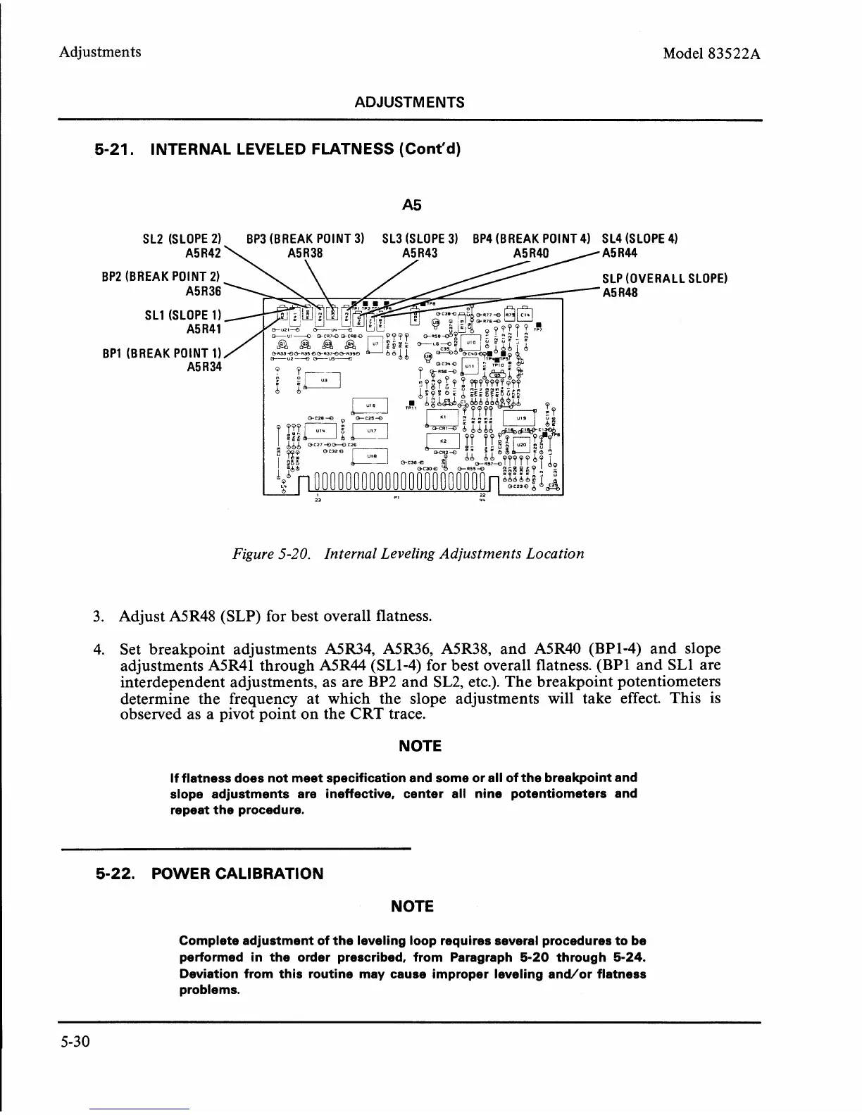
Figure
5-20.
Internal Leveling Adjustments Location
3. Adjust A5R48 (SLP) for best overall flatness.
4. Set breakpoint adjustments
A5R34, A5R36, A5R38, and A5R40 (BPI-4) and slope
adjustments
A5R41 through A5R44 (SL1-4) for best overall flatness. (BPI and SLl are
interdependent adjustments, as are BP2 and SL2, etc.). The breakpoint potentiometers
determine the frequency at which the slope adjustments will take effect. This is
observed as a pivot point on the CRT trace.
NOTE
If flatness does not meet specification and some or all of the breakpoint and
slope adjustments are ineffective, center all nine potentiometers and
repeat the procedure.
5-22.
POWER CALIBRATION
NOTE
Complete adjustment of the leveling loop requires several procedures to be
performed in the order prescribed, from Paragraph
5-20
through
5-24.
Deviation from this routine may cause improper leveling andlor flatness
problems.