Model
83522A
Operation
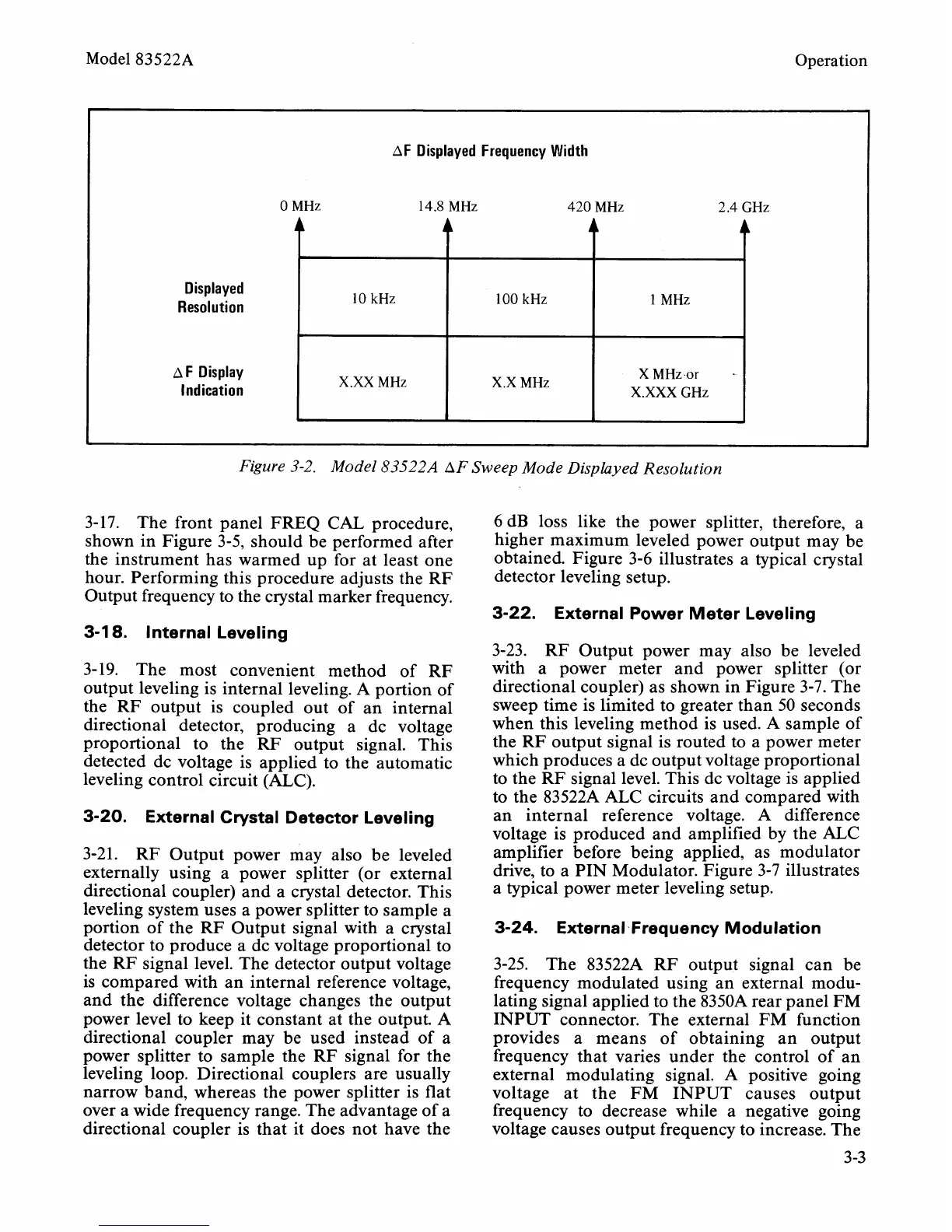
AF Displayed Frequency Width
0 MHz 14.8 MHz 420 MHz 2.4 GHz
Figure 3-2. Model 83522A AF Sweep Mode Displayed Resolution
1
Displayed
Resolution
A
F Display
Indication
Ir
A
4
3-17. The front panel FREQ CAL procedure,
shown in Figure 3-5, should be performed after
the instrument has warmed up for at least one
hour. Performing this procedure adjusts the RF
Output frequency to the crystal marker frequency.
L
3-1
8.
Internal Leveling
1
MHz
X
MHza
-
X.XXX
GHz
10 kHz
X.XX
MHz
3-19. The most convenient method of RF
output leveling is internal leveling. A portion of
the RF output is coupled out of an internal
directional detector, producing a dc voltage
proportional to the RF output signal. This
detected dc voltage is applied to the automatic
leveling control circuit (ALC).
100 kHz
X.X
MHz
3-20. External Crystal Detector Leveling
3-21.
RF Output power may also be leveled
externally using a power splitter (or external
directional coupler) and a crystal detector. This
leveling system uses a power splitter to sample a
portion of the RF Output signal with a crystal
detector to produce a dc voltage proportional to
the RF signal level. The detector output voltage
is compared with an internal reference voltage,
and the difference voltage changes the output
power level to keep it constant at the output.
A
directional coupler may be used instead of a
power splitter to sample the RF signal for the
leveling loop. Directional couplers are usually
narrow band, whereas the power splitter is flat
over a wide frequency range. The advantage of a
directional coupler is that it does not have the
6 dB loss like the power splitter, therefore, a
higher maximum leveled power output may be
obtained. Figure 3-6 illustrates a typical crystal
detector leveling setup.
3-22. External Power Meter Leveling
3-23.
RF Output power may also be leveled
with a power meter and power splitter (or
directional coupler) as shown in Figure 3-7. The
sweep time is limited to greater than 50 seconds
when this leveling method is used.
A
sample of
the RF output signal is routed to a power meter
which produces a dc output voltage proportional
to the RF signal level. This dc voltage is applied
to the
83522A ALC circuits and compared with
an internal reference voltage.
A
difference
voltage is produced and amplified by the ALC
amplifier before being applied, as modulator
drive, to a PIN Modulator. Figure 3-7 illustrates
a typical power meter leveling setup.
3-24. External-Frequency Modulation
3-25. The 83522A RF output signal can be
frequency modulated using an external modu-
lating signal applied to the
8350A rear panel FM
INPUT connector. The external FM function
provides a means of obtaining an output
frequency that varies under the control of an
external modulating signal. A positive going
voltage at the FM INPUT causes output
frequency to decrease while a negative going
voltage causes output frequency to increase. The