Model
83522A
ADJUSTMENTS
Adjustments
5-23.
POWER METER LEVELING CALIBRATION
NOTE
Complete adjustment of the leveling loop for Power Meter leveling requires
several procedures to be performed in the order prescribed from Psragraph
5-20 through 5-24. Deviation from this routine may cause improper leveling
andlor flatness problems.
REFERENCE:
Performance Test:
8350A Paragraph 4-14.
Service Sheet: A4
DESCRIPTION:
Power Meter leveling gain potentiometer
A4R9
(PM)
calibrates loop gain to full-scale
deflection
of
the leveling meter.
EQUIPMENT:
Sweep Oscillator
.....................................................
HP 8350A
Power Meter.
.........................................................
HP
432A
Thermistor Mount.
....................................................
HP 478A
10 dB Attenuator..
........................................
HP 8491A Option 010
PROCEDURE:
NOTE
If, during the following procedure, ALC loop oscillations occur, reduce loop
gain
by
adjusting A4R11 (Figure
5-26)
counterclockwise. This adjustment
will be set in the next procedure.
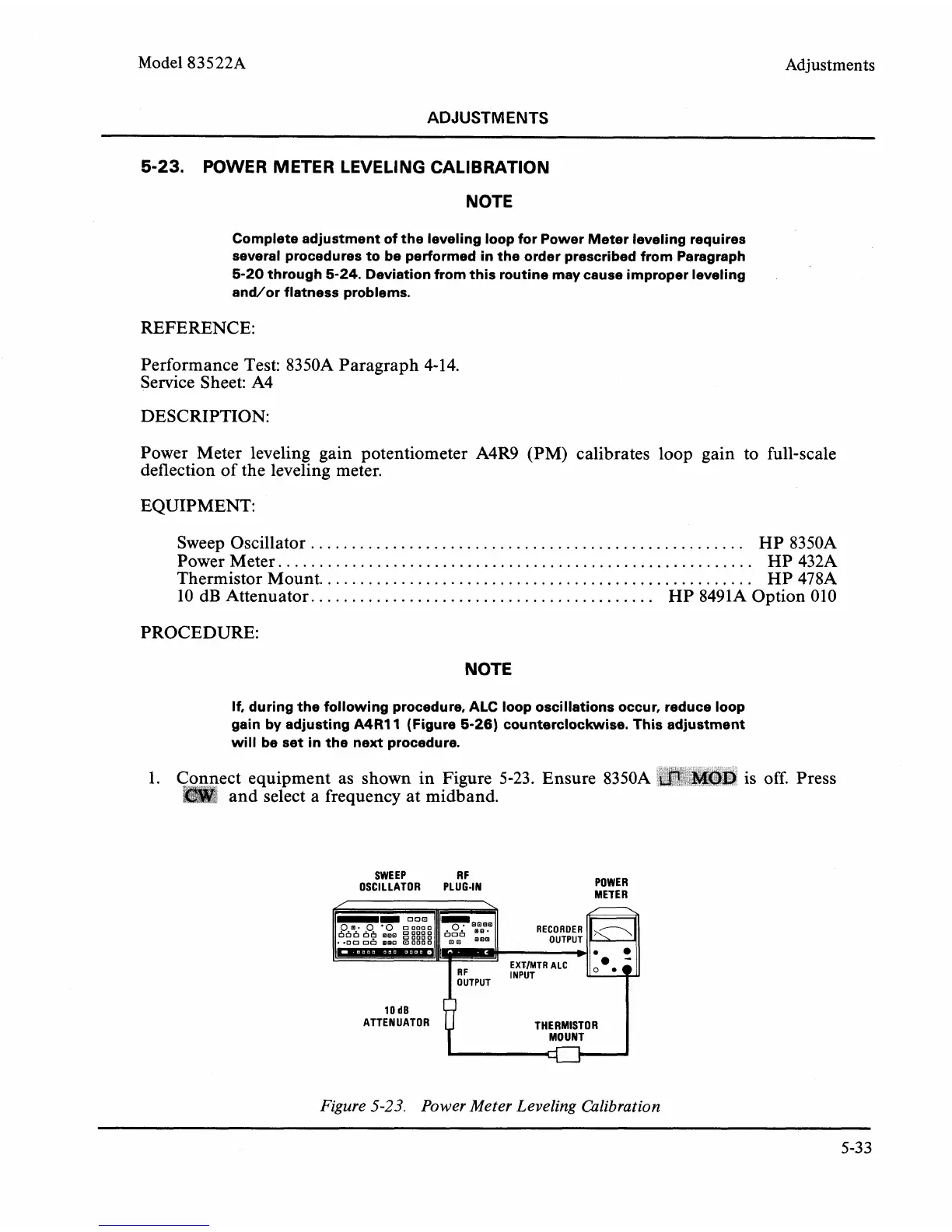
1.
ect equipment
as
shown in Figure
5-23.
Ensure 8350A is
off.
Press
and select a frequency at
midband.
SWEEP R
F
OSCILLATOR PLUG-IN
POWER
METER
.,
RF
-
INPUT
OUTPUT
-
I
ATTEN UATOR THERMISTOR
MOUNT
I
Figure
5-23.
Power Meter Leveling Calibration
5-33