Adjustments
ADJUSTMENTS
Model
83522A
5-26.
FM
DRIVER
(Cont'd)
9.
Manually sweep function generator frequency from DC to 10 MHz. Adjust A5C14
"LO" and A5R75 "HI" controls several times (Figure 5-30) to obtain the most constant
overall response from DC to 10 MHz.
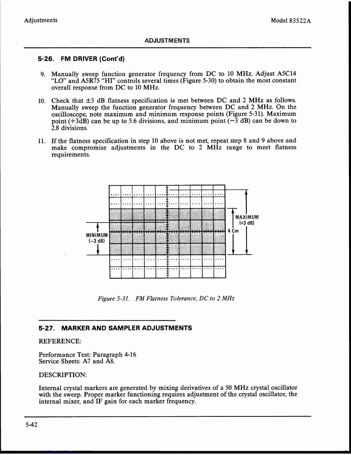
10. Check that +3 dB flatness specification is met between DC and
2
MHz as follows.
Manually sweep the function generator frequency between DC and
2
MHz. On the
oscilloscope, note maximum and minimum response points (Figure 5-3 1). Maximum
point
(+3dB) can be up to 5.6 divisions, and minimum point (-3 dB) can be down to
2.8
divisions.
11. If the flatness specification in step 10 above is not met, repeat step
8
and
9
above and
make compromise adjustments in the DC to
2
MHz range to meet flatness
requirements.
MINIMUM
(-3
dB)
MAXIMUM
(+3
dB)
Figure
5-31.
FM Flatness Tolerance,
DC
to
2
MHz
5-27.
MARKERANDSAMPLERADJUSTMENTS
REFERENCE:
Performance Test: Paragraph 4-1 6
Service Sheets: A7 and
A8.
DESCRIPTION:
Internal crystal markers are generated by mixing derivatives of a 50 MHz crystal oscillator
with the sweep. Proper marker functioning requires adjustment of the crystal oscillator, the
internal mixer, and IF gain for each marker frequency.