Model 83522A
ADJUSTMENTS
Adjustments
5-26.
FM DRIVER (Cont'd)
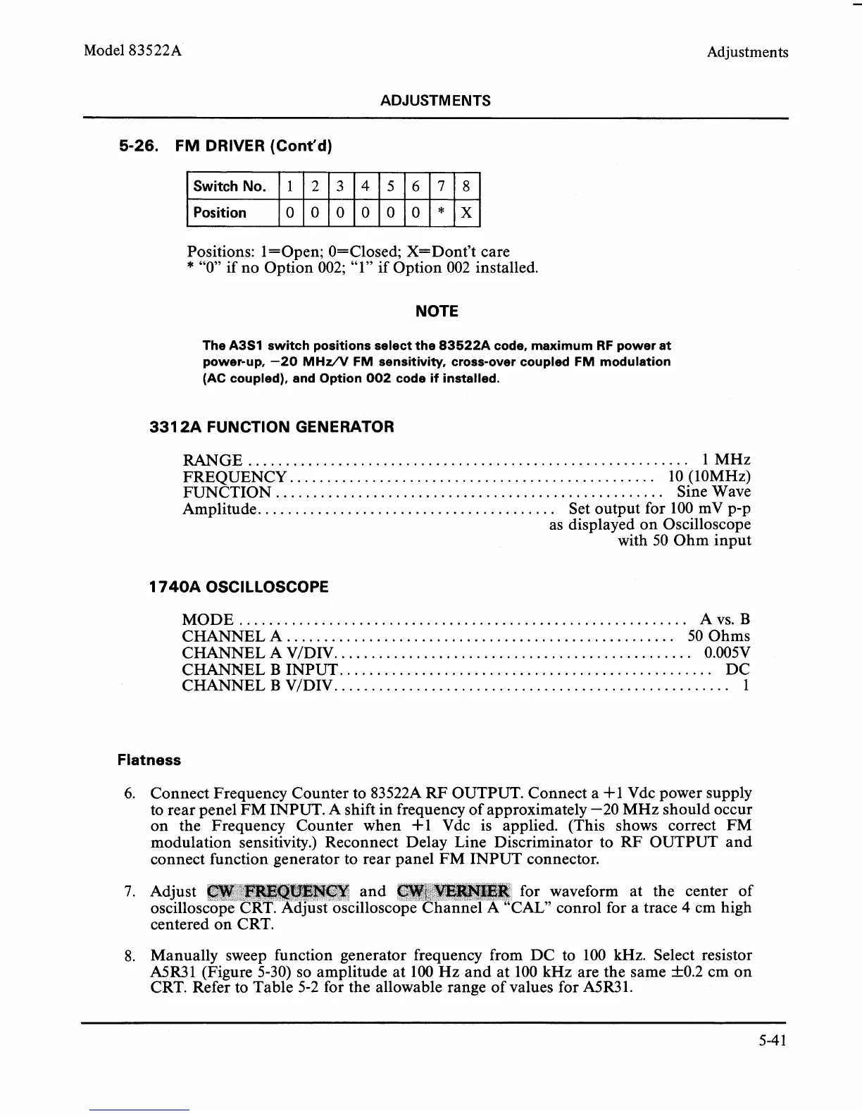
Positions: l=Open; O=Closed; X=Dont't care
*
"0" if no Option 002; "1" if Option 002 installed.
SwitchNo.
Position
NOTE
The
A3S1
switch positions select the
83522A
code, maximum RF power at
power-up,
-20
MHzA/ FM sensitivity, cross-over coupled FM modulation
(AC
coupled), and Option
002
code if installed.
1
331
2A FUNCTION GENERATOR
...........................................................
RANGE 1 MHz
................................................
FREQUENCY. 10 (IOMHz)
....................................................
FUNCTION Sine Wave
.......................................
Amplitude.
Set output for 100
mV p-p
as displayed on Oscilloscope
with 50 Ohm input
2
1
740A OSCILLOSCOPE
............................................................
MODE A vs.
B
CHANNEL A
....................................................
50 Ohms
CHANNEL A
V/DIV.
...............................................
0.005V
CHANNEL
B
INPUT.
.................................................
DC
CHANNEL
B
VIDIV..
...................................................
1
3
Flatness
6.
Connect Frequency Counter to 83522A RF OUTPUT. Connect a i-1 Vdc power supply
to rear
penel FM INPUT. A shift in frequency of approximately -20 MHz should occur
on the Frequency Counter when
+1 Vdc is applied. (This shows correct FM
modulation sensitivity.) Reconnect Delay Line Discriminator to RF OUTPUT and
connect function generator to rear panel FM INPUT connector.
4
OOOOOO*X
7.
Adjust and for waveform at the center of
oscillos illosc
AL"
conrol for a trace
4
cm high
centered on CRT.
8. Manually sweep function generator frequency from DC to 100 kHz. Select resistor
A5R.31 (Figure 5-30) so amplitude at
100
Hz and at 100 kHz are the same k0.2 cm on
CRT. Refer to Table 5-2 for the allowable range of values for
A5R31.
5
7
6
8