Adjustments
Model
83522A
ADJUSTMENTS
5-26.
FM
DRIVER
(Cont'd)
2.
Place
A5
FM Driver on extender board.
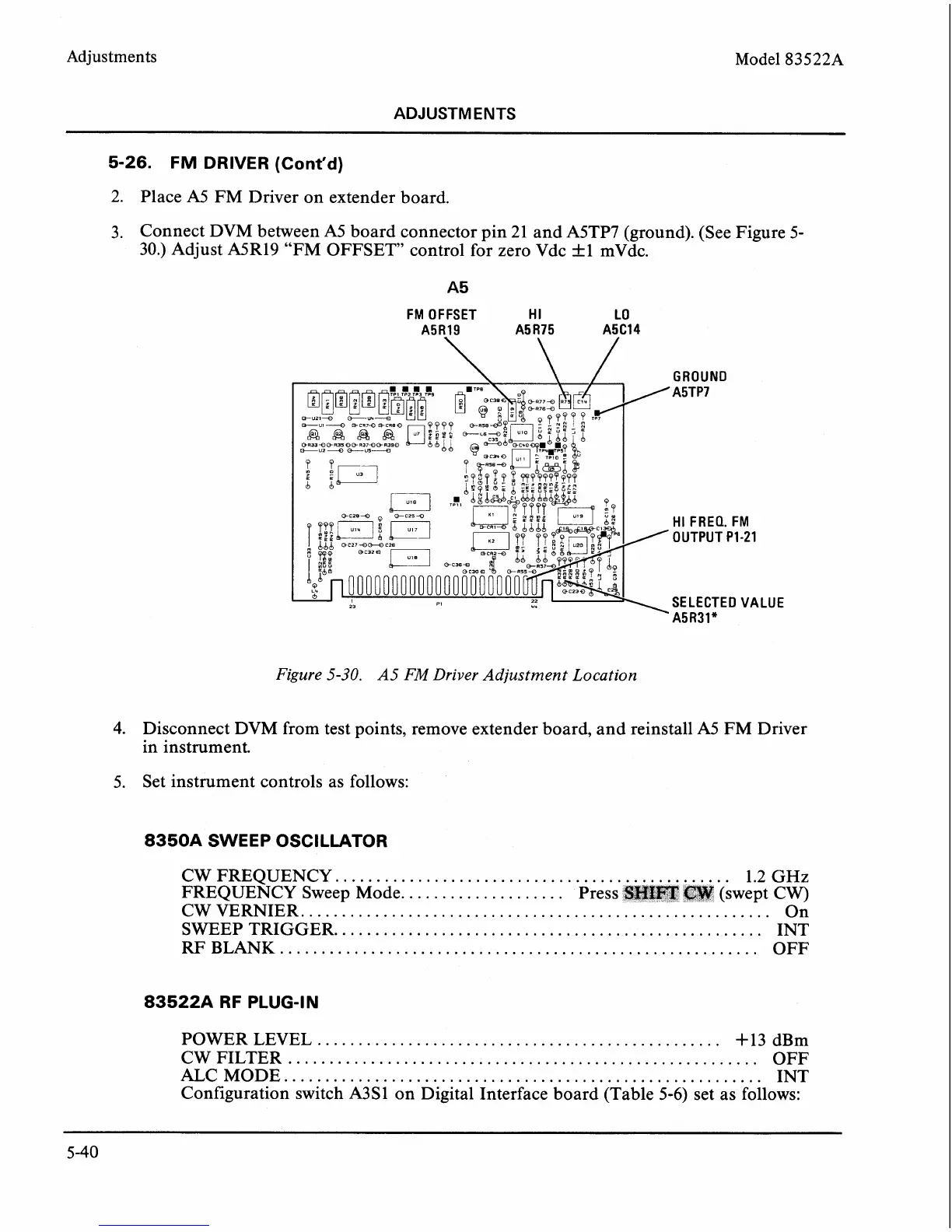
3. Connect DVM between A5 board connector pin
21
and A5TP7 (ground). (See Figure 5-
30.) Adjust A5R19 "FM OFFSET control for zero Vdc +1 mVdc.
FM OFFSET
HI
LO
A5R19 A5 R75 A5C14
GROUND
A5TP7
HI
FREQ. FM
OUTPUT PI-21
SELECTED VALUE
A5R31"
Figure
5-30.
A5
FM
Driver
Adjustment
Location
4.
Disconnect DVM from test points, remove extender board, and reinstall A5 FM Driver
in instrument.
5. Set instrument controls as follows:
8350A SWEEP OSCILLATOR
CW FREQUENCY..
..............................................
1.2 GHz
FREQUENCY Sweep Mode.
...................
Pres
CW VERNIER.
.....................................
SWEEP TRIGGER.
...................................................
INT
RF
BLANK..
........................................................
OFF
83522A RF PLUG-IN
POWER LEVEL
.................................................
+
13 dBm
CW FILTER
.........................................................
OFF
ALC MODE..
........................................................
INT
Configuration switch
A3S1 on Digital Interface board (Table 5-6) set as follows: