Operation Model 83522A
Figure
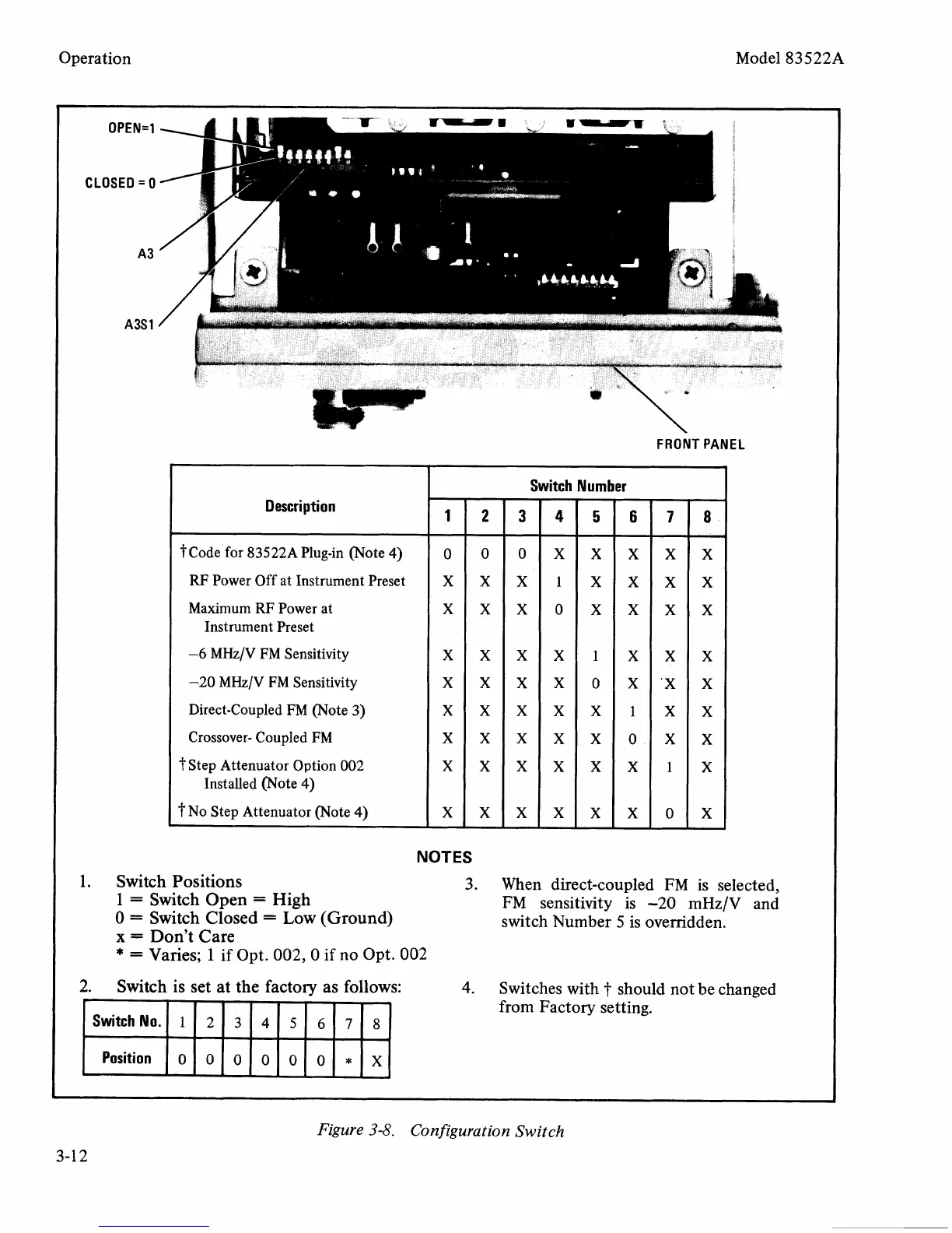
3-8.
Configuration Switch
NOTES
1.
Switch Positions
3. When direct-coupled FM is selected,
1
=
Switch Open
=
High
FM sensitivity is -20
mHz/V
and
0
=
Switch Closed
=
Low
(Ground)
switch Number
5
is overridden.
x
=
Don't Care
*
=
Varies;
1
if Opt. 002, 0
if
no Opt. 002
2.
Switch is set at the factory as follows:
4.
Switches with
t
should not be changed
from Factory setting.
Switch
Number
Description
12345678
I
,
t~ode for 83522APlug-in (Note 4)
0
0
0 X X X X X
RF
Power Off at Instrument Preset
X X X
1
X
X X
X
Maximum
RF
Power at
XXXOXXXX
Instrument Preset
-6
MHz/V FM Sensitivity
-20
MHz/V FM Sensitivity
Direct-Coupled FM (Note 3)
Crossover- Coupled FM
%tep Attenuator Option
002
Installed (Note 4)
?No Step Attenuator (Note
4)
XXXXlXXX
XXXXOX'XX
XXXXXlXX
XXXXXOXX
XXXXXXlX
XXXXXXOX