Service
Model
83522A
Flatness/Oscillations (Power Drop-outs)
Monitor the RF output with the
HP
8755C as shown in Fig. 8-26.
If the power level is constant across the sweep within approximately 5 dB,
then the plug-in may only require ALC flatness adjustments. Refer to
Section V, Adjustments, in this manual, for the Internal Leveled Flatness
adjustment procedure.
If the measured power level lies between 4-13 and
-2
dBm, but can't be
controlled via the front panel, refer to the Digital Control section under
Troubleshooting Diagnosis.
If the trace appears chopped or broken the loop may be oscillating. Refer to
Section V, Adjustments, in this manual, and perform the ALC Gain
adjustment procedure.
Full Unleveled
Power
Set the 83522A to sweep the full range.
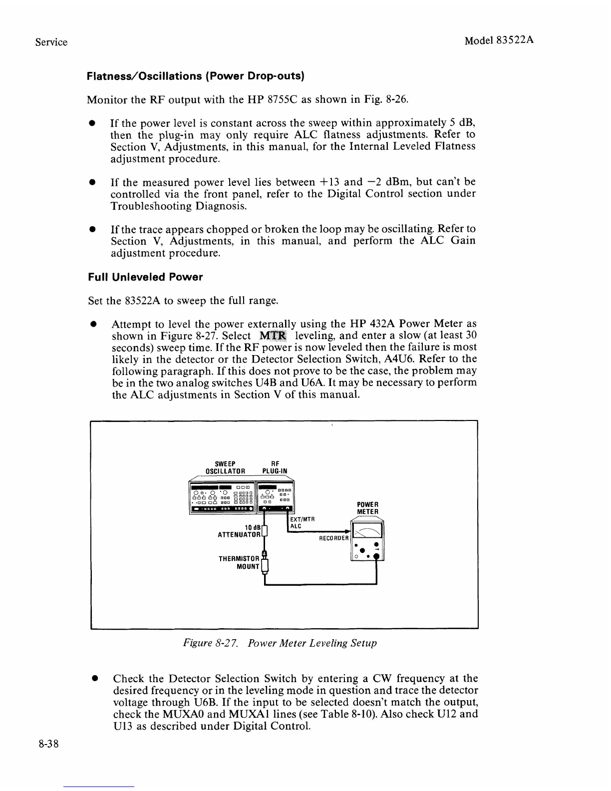
Attempt to level the power externally using the
HP
432A Power Meter as
shown in Figure 8-27. Select
MTR
leveling, and enter a slow (at least 30
seconds) sweep time. If the RF power is now leveled then the failure is most
likely in the detector or the Detector Selection Switch,
A4U6. Refer to the
following paragraph. If this does not prove to be the case, the problem may
be in the two analog switches U4B and
U6A. It may be necessary to perform
the ALC adjustments in Section V of this manual.
SWEEP
R
F
OSCILLATOR PLUG-IN
/
\
POWER
MOUNT
u
Figure
8-2
7.
Power Meter Leveling Setup
Check the Detector Selection Switch by entering a CW frequency at the
desired frequency or in the leveling mode in question and trace the detector
voltage through
U6B. If the input to be selected doesn't match the output,
check the MUXAO and
MUXAl lines (see Table 8-10). Also check U12 and
U13
as described under Digital Control.