Service
Model
83522A
-
w
I
-460 psec
.
.
I
1
-
28 psec
LEN
0
I
-40 psec
j
(Not Used)
I
I
I
LEN
1
I
I
(Not Used)
I
I
I
LEN2
1
I
I
(Not Used)
1
I
I
LEN3
1
I
(Not Used)
I
I I
I
LEN
5
I
I
I
U18-10
I
I
I
LEN
6
(Not Used)
Enter:
SH
l
FT
54
Trigger: LEN
fl
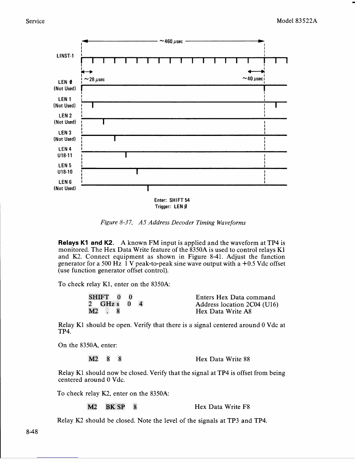
Figure
8-3
7.
A5
Address Decoder Timing Waveforms
Relays
K1
and
K2.
A known
FM
input is applied and the waveform at TP4 is
monitored. The Hex Data Write feature of the
8350A is used to control relays K1
and
K2.
Connect equipment as shown in Figure 8-41. Adjust the function
generator for
a
500 Hz 1 V peak-to-peak sine wave output with a i-0.5 Vdc offset
(use function generator offset control).
To check relay
K1,
enter on the 8350A:
SHIFT
0
0
Enters Hex Data command
2
GHzs
0
4
Address location 2C04 (U16)
M2
.
8
Hex Data Write A8
Relay Kl should be open. Verify that there is
a
signal centered around 0 Vdc at
On the
83504 enter:
M2
8
8
Hex Data Write 88
Relay
K1 should now be closed. Verify that the signal at TP4 is offset from being
centered around
0
-
Vdc.
To check relay
K2,
enter on the 8350A:
M2
BKSP
8
Hex Data Write F8
Relay
K2
should be closed. Note the level of the signals at TP3 and TP4.
 Loading...


