Service Model 83522A
A1
4
AMPLIFIER
Check for power input as described under A17, above. Verify
RF
output at
approximately
+20 dBm unleveled with high harmonic distortion. When trying
to isolate harmonic sources, refer to A4 Troubleshooting and follow the Open
Loop Procedure. This procedure externally biases the modulators to level the
RF power under open loop conditions.
A1
5
DC RETURN
An A15 failure is extremely unlikely. However, this component can be tested
OUT OF CIRCUIT with an ohmmeter. Verify DC short to ground.
DC1 DIRECTIONAL DETECTOR
Check for approximately
+
15 dBm of leveled output power. Ensure that power
is nominally
i-13 dBm and check the detector output, E2, for approximately
-0.2 Vdc or more negative. If temperature drift is suspected, check that the INT
DET
0 BIAS adjustment (A4R4) has an effect on the detected output level. If it
does not, replace
DC1.
A1
9
STEP ATENUATOR (Option
002
Only)
Check the output of DC2 for approximately +13 dBm. Verify that
A3
Configuration Switch is set for Option 002 (see A3 Service Sheet, Table 8-8). Set
the
8350A front panel step keys,
r
*,
for 10 dB steps. Increment the power
setting with the step keys to run the attenuator through its 70 dB range. (Power
meters will typically NOT have the dynamic range to verify this operation.) The
control circuits can be manually exercised by operating the sweep oscillator in
the CW mode and performing a Hex Data Write to address
2F00. Enter two hex
digits in the format "Ox", where 00 equates with
0 dB attenuation, 01 with 10 dB
attenuation, 02 with 20 dB attenuation, and so on.
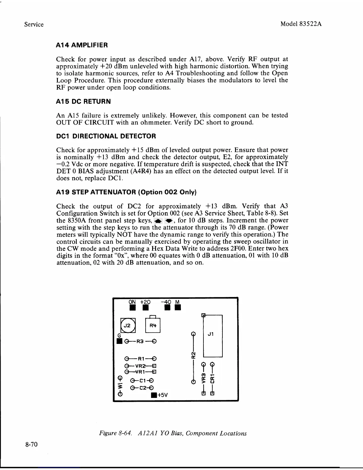
Figure
8-64.
A12Al
YO
Bias, Component Locations
8-70
 Loading...


