Model 83522A
Table
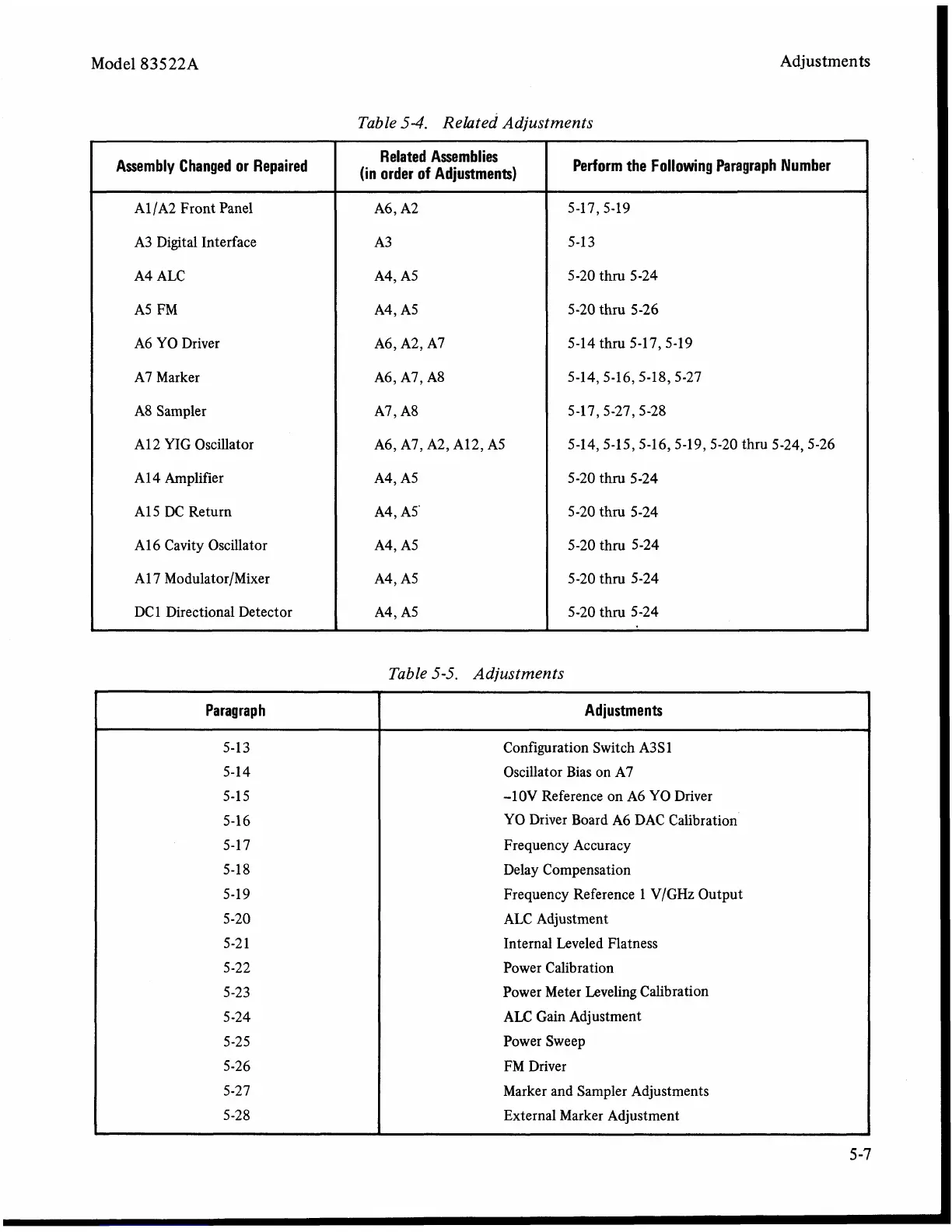
5-4.
Related Adjustments
Adjustments
Table5-5. Adjustments
Assembly Changed or Repaired
A1 /A2 Front Panel
A3 Digital Interface
A4 ALC
A5
FM
A6 YO Driver
A7 Marker
A8 Sampler
A12 YIG Oscillator
A1 4 Amplifier
A1 5 DC Return
A1 6 Cavity Oscillator
A1 7
Modulator/Mixer
DC1 Directional Detector
Related Assemblies
(in order of Adjustments)
A6, A2
A3
A4, A5
A4, A5
A6, A2, A7
A6, A7, A8
A7, A8
A6, A7, A2, A12, A5
A4, A5
A4,
A5'
A4, A5
A4, A5
A4, A5
b
Paragraph
5-13
5- 14
5-1 5
5-16
5-17
5-18
5-19
5-20
5-2 1
5-22
5-23
5 -24
5-25
5-26
5-27
5-28
2
Perform the Following Paragraph Number
5-17,5-19
5-1 3
5-20
thm 5-24
5-20
thr~ 5-26
5-14 thru
5-17,s-19
5-14,5-16,5-18,5-27
5-17,5-27,5-28
5-14,s-15,5-16,5-19,5-20
thru 5-24,5-26
5-20 thru 5-24
5-20
thr~ 5-24
5-20
thru 5-24
5-20
thm 5-24
5-20
thm 5-24
Adjustments
I
Configuration Switch A3S 1
Oscillator Bias on A7
-lOV Reference on A6
YO
Driver
YO Driver Board
A6
DAC Calibration
Frequency Accuracy
Delay Compensation
Frequency Reference 1
V/GHz Output
ALC Adjustment
Internal Leveled Flatness
Power Calibration
Power Meter Leveling Calibration
ALC
Gain Adjustment
Power Sweep
FM Driver
Marker and Sampler Adjustments
External Marker Adjustment