Model
83522A
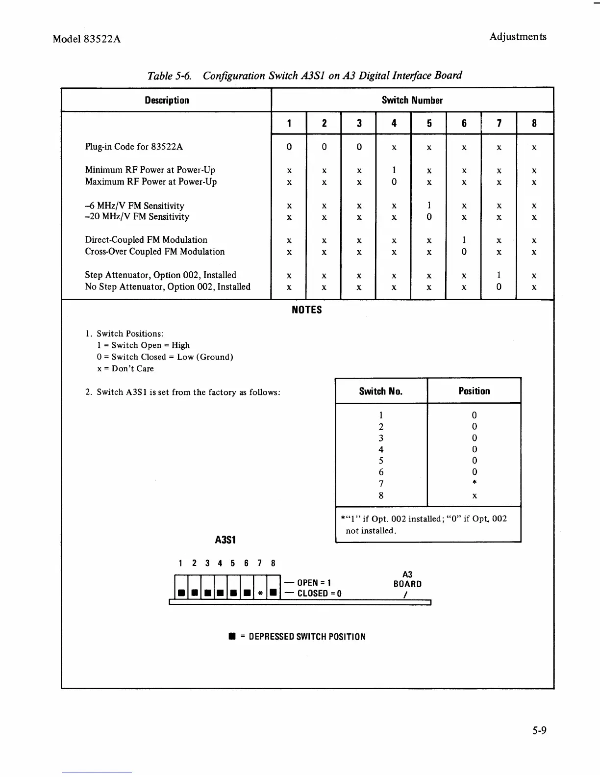
Table
5-6.
Configuration Switch
A3Sl
on
A3
Digital In tet$ace Board
Adjustments
Description
Plug-in Code for 83522A
Minimum RF Power at Power-Up
Maximum RF Power at Power-Up
-6
MHz/V FM Sensitivity
-20
MHz/V FM Sensitivity
Direct-Coupled FM Modulation
Cross-Over Coupled FM Modulation
Step Attenuator, Option
002,
Installed
No Step Attenuator, Option
002,
Installed
Switch Number
1
0
x
x
x
x
x
x
x
x
NOTES
1. Switch Positions:
1
=
Switch Open
=
High
0
=
Switch Closed
=
Low (Ground)
x
=
Don't Care
2. Switch
A3S
1 is set from the factory as follows:
A3S1
2
0
x
x
x
x
x
x
x
x
Switch NO.
1
2
3
4
5
6
7
8
3
0
x
x
x
x
x
x
x
x
Position
0
0
0
0
0
0
*
x
12345678
A3
*"I
"
if Opt. 002 installed
;
"0" if Opt 002
not installed.
.
-
OPEN
=
1 BOARD
--CLOSED=O
/
4
x
1
0
x
x
x
x
x
x
I
1
=
DEPRESSED SWITCH POSITION
6
x
x
x
x
x
1
0
x
x
5
x
x
x
1
0
x
x
x
x
*
.
.
7
x
x
x
x
x
x
x
1
0
8
x
x
x
x
x
x
x
x
x
.
.
.