Adjustments
Model
83522A
ADJUSTMENTS
5-1
6. YO DRIVER BOARD A6 DAC CALIBRATION
REFERENCE:
Performance Test:
8350A Paragraph 4-13.
Service Sheet: A6
DESCRIPTION:
Adjustments are made to remove offsets and calibrate OFFSET and SLOPE DAC step sizes.
EQUIPMENT:
Sweep Oscillator
.....................................................
HP 8350A
Digital Voltmeter (DVM)
.............................................
HP 3455A
PROCEDURE:
NOTE
YO Driver Board adjustments should be avoided if possible. Set up
equipment as shown in Figure
5-8
and perform step
23
in Paragraph
5-1
7
to check frequency accuracy and sweep linearity across the band. If
frequencies are within
+5
MHz
tolerance, do not make these YO Driver
Board adjustments.
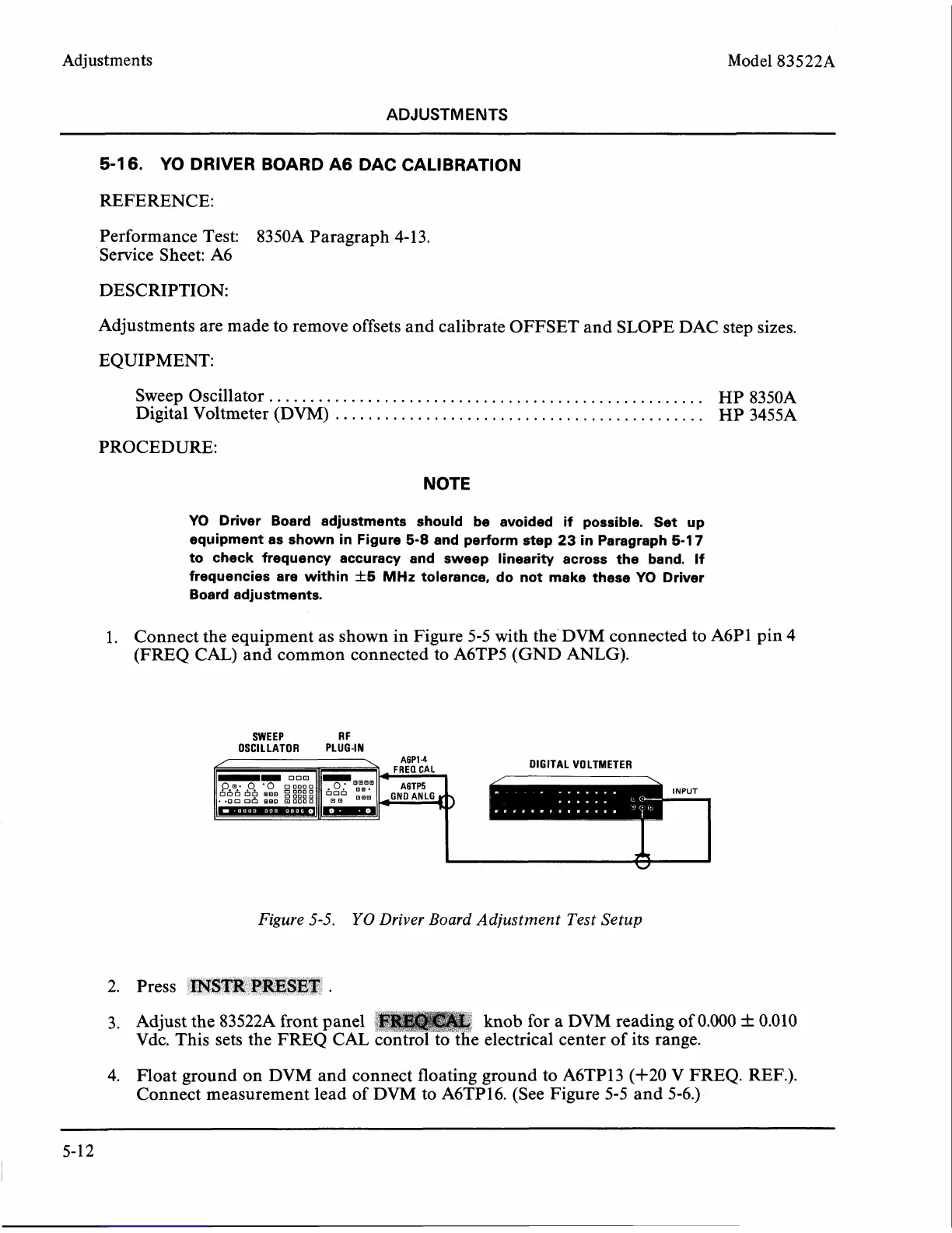
1.
Connect the equipment as shown in Figure 5-5 with the DVM connected to A6P1 pin 4
(FREQ
CAL)
and common connected to A6TP5 (GND
ANLG).
SWEEP R
F
OSCILLATOR PLUG-IN
DIGITAL VOLTMETER
Figure
5-5.
YO
Driver Board Adjustment Test Setup
2. Press
INSTR
PRESET
.
3. Adjust the 83522A front panel
:
knob for a DVM reading of 0.000
+_
0.010
Vdc. This sets the FREQ
CAL control to the electrical center of its range.
4. Float ground on DVM and connect floating ground to
A6TP13 (+20 V FREQ. REF.).
Connect measurement lead of DVM to
A6TP16. (See Figure 5-5 and 5-6.)