Model
8754A
Set CRT Display
The CH I and CH 2
buttons
are pressed
to
select display
of
the
rectangular reference position line for each channel instead
of
the measurement trace. They provide a means
to
identify
the
trace for each channel,
and
to
establish
the
vertical position
which corresponds
to
the
REFERENCE value
readout
on
the
corresponding lever switches.
Screwdriver adjustments are provided
to
adjust
the
position
(POSN) and
the
length (GAIN)
of
the
horizontal sweep when
making rectangular measurements.
Front
Panel
Introduction
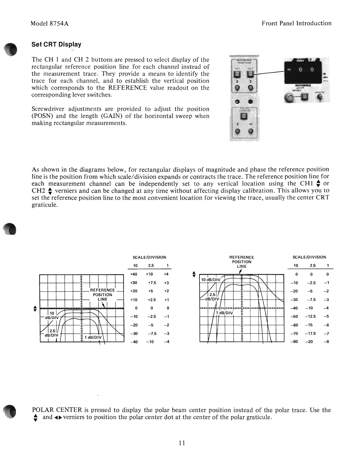
As
shown
in the
diagrams
below,
for
rectangular displays
of
magnitude
and
phase
the reference position
line is the position
from
which scale/division expands
or
contracts
the trace.
The
reference
position
line for
each
measurement
channel
can
be independently set
to
any
vertical
location
using the
CH
1
~
or
CH2
~
verniers
and
can
bevChanged
at
any
time
without
affecting display calibration. This allows
you
to
set the reference
position
line
to
the
most
convenient
location
for
viewing the trace, usually the center
CRT
graticule.
SCALE/DIVISION
10
2.5
+40
+10
+4
•
•
+30
+7.5
+3
+20 +5
+2
+10 +2.5
+1
•
0 0 0
•
-10
-2.5
-1
-20
-5
-2
-30
-7.5
-3
-40
-10
-4
REFERENCE
POSITION
LINE
I
I
I,...
--
~
10
dB/DIV
/""
"""-
VI
V
---=
",...-
\ \i'..
1\
vj.2.511/
,
",
f-dB/Orl.
........
~,
II'
1\
'\
1 dB/DIV
I I
\ '
/
II
\ \
V
\
\
SCALE/DIVISION
10
2.5
0 0 0
.
-10
-2.5
-1
-20
-5 -2
-30
-7.5
-3
-40
-10
-4
-50
-12.5
-5
-60
-15
-6
-70
-17.5
-7
-80
-20
-8
POLAR CENTER
is
pressed
to
display
the
polar beam
center
position instead
of
the
polar trace. Use
the
~
and
~~
verniers
to
position
the
polar
center
dot
at
the
center
of
the
polar graticule.
11
Artisan Technology Group - Quality Instrumentation ... Guaranteed | (888) 88-SOURCE | www.artisantg.com