14
After calibration, the OFFSET vernier should
not
be moved
or
calibration will no longer be valid.
~fodel
8754A
Any device with known characteristics may be used as a calibration standard. The usual calibration stan-
dard
for transmission measurements
is
a
"through"
connection (connect the points
at
which the test device
will be connected
to
achieve a zero length, zero loss transmission line). The usual
standard
for reflection
measurements
is
a
short
circuit
at
the measurement plane (connect the short circuit
at
the point
at
which the
test device will be connected). Thus, calibration establishes the magnitude
and
phase response
of
the test
setup
to
a known value. All cables, adapters etc. used in calibration must also be used in measurement
or
the calibration will
not
be exact.
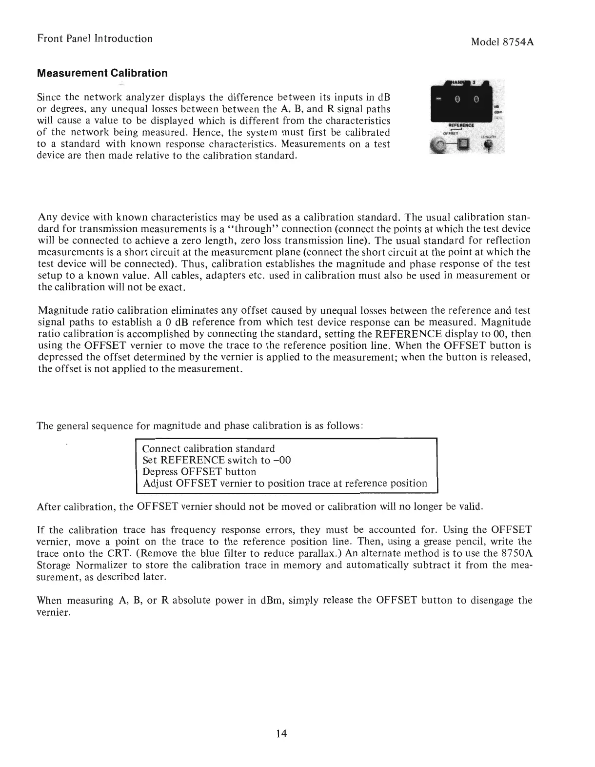
Connect calibration standard
Set REFERENCE switch
to
-00
Depress OFFSET
button
Adjust OFFSET vernier
to
position trace
at
reference position
Magnitude ratio calibration eliminates any offset caused by unequal losses between the reference
and
test
signal paths
to
establish a 0 dB reference from which test device response can be measured. Magnitude
ratio calibration?is accomplished by connecting the
standard,
setting the
REFERENCE
display
to
00, then
using the
OFFSET
vernier
to
move the trace
to
the reference position line. When the
OFFSET
button
is
depressed the offset determined by the vernier
is
applied to the measurement; when the
button
is
released,
the offset
is
not
applied
to
the measurement.
Front
Panel Introduction
Measurement Calibration
When measuring
A,
B,
or
R absolute power in dBm, simply release the OFFSET
button
to
disengage
the
vernier.
Since the network analyzer displays the difference between its inputs in
dB
or
degrees, any unequal losses between between
the
A,
B,
and R signal paths
will cause a value
to
be displayed which
is
different from the characteristics
of
the
network
being measured. Hence,
the
system must first be calibrated
to
a standard with known response characteristics. Measurements on a test
device are then made relative
to
the calibration standard.
If
the calibration trace has frequency response errors,
they
must be accounted for. Using
the
OFFSET
vernier, move a
point
on the trace
to
the
reference position line. Then, using a grease pencil, write
the
trace
onto
the CRT. (Remove
the
blue filter
to
reduce parallax.) An alternate
method
is
to
use
the
8750A
Storage Normalizer
to
store
the
calibration trace in memory and automatically subtract
it
from the mea-
surement,
as
described later.
The general sequence for magnitude and phase calibration
is
as
follows:
Artisan Technology Group - Quality Instrumentation ... Guaranteed | (888) 88-SOURCE | www.artisantg.com