Model
8754A
Front
Panel
Introd~ction
You may continue this sequence
at
sweep width positions below 20 MHz and use
the
1 MHz markers
to
set
the readout with greater precision. The center
of
the
marker,
not
the
leading
or
trailing edge, indicates
the
50, 10,
or
1
MHz
harmonic frequency.
Another
use for
the
crystal markers is
to
set an intermediate sweep width. Select a sweep width one step
higher
than
the width
you
require and select appropriate markers,
then
adjust
the
inner sweep width vernier
counterclockwise from
the
CAL position
to
achieve
the
desired width.
Set Signal Levels
Source Output Power. The
output
dBm
control
sets
the
source
output
level
at
the
RF
OUTPUT connector.
This
output
is
internally leveled between 0 dBm and +10 dBm. External precision
attenuation,
such
as
incorporated in the 8502A/B and
8748A
test sets, may be used
to
control
the
incident signal level
at
the
test device.
Input Power. Maximum power which should be applied
to
the
R,
A,
and B inputs
is
0 dBm. Above 0 dBm,
measurement errors may result from
input
sampler compression. To maintain receiver phase-lock,
the
R
input
level must be between 0 dBm and
-40
dBm. The red UNLOCI(ED indicator will light when
the
R
input
falls below
-40
dBm.
The A and B inputs are identical, each with a 0 dBm
to
-80
dBm range. Best measurement accuracy
is
achieved when
the
R
input
is between 0 and
-30
dBm and
the
A
or
B test inputs are near maximum.
For
example, dynamic accuracy is ±2.5
dB
with
the
test
input
level
at
-75
dBm
but
improves
to
±0.3 dB
above
-50
dBm.
Measurement uncertainty caused
by
crosstalk between inputs can become
important
when
the
signal
levels differ significantly.
For
example, with
the
R
input
at
0 dBm and
the
B
input
at
-75
dBm,
the
mea-
surement uncertainty
contributed
by
crosstalk is
about
1 dB. This uncertainty can be reduced
to
"about
0.1 dB
by
reducing
the
R
input
level
to
-30
dBm.
The
input
level
at
calibration determines
the
available measurement range without overload
or
excessive
measurement uncertainty.
For
reflection measurements and transmission loss measurements,
the
incident
signal level should be
as
high
as
the
test device characteristics will permit.
For
gain measurements, set
the
incident signal level
to
a value
at
which
the
expected device
output
will
not
exceed 0 dBm at
the
A
or
B
input.
When using
the
8502A/Bor
8748A
test sets,
the
incident signal can be
attenuated
without
reducing
the
signal level
at
the
R input.
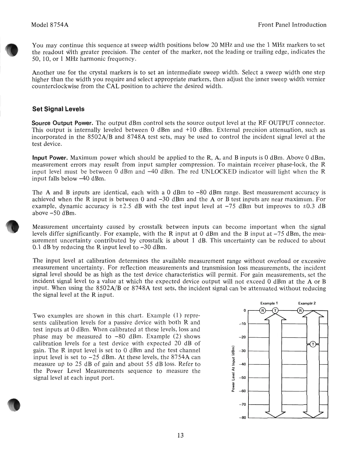
Two examples are shown in this chart. Example (1) repre-
sents calibration levels for a passive device with
both
Rand
test inputs at 0 dBm. When calibrated
at
these levels, loss and
phase may be measured
to
-80
dBm. Example (2) shows
calibration levels for a test device with expected 20
dB
of
gain. The R
input
level
is
set
to
0 dBm and
the
test channel
input
level
is
set
to
-25
dBm.
At
these levels,
the
8754A
can
measure up
to
25 dB
of
gain and
about
55 dB loss. Refer
to
the
Power Level Measurements sequence
to
measure
the
signal level at each
input
port.
Example 1
Example 2
0
-10
-20
E
-30
OJ
:9.
....
:::J
~
.:
-40
~
a:;
>
-50
Q)
..J
...
Q)
~
0
-60
0-
-70
-80
13
Artisan Technology Group - Quality Instrumentation ... Guaranteed | (888) 88-SOURCE | www.artisantg.com