Modulate
or
Sum
the
Signals
2-5
Set
Up
the
Modulation Signal
3.
Press the
NEXT
key
to
access the Channel
B
Configuration
display.
Note
Note
Only Channel
A
can be modulated. However, any
or
all
of
the
remaining channels
(B,
C
and
0)
can be used
for
modulating
Channel
A.
4.
Press the blue
SHIFT
key
and
then the
DESTN
key.
The
HP
8904A is now ready for you to specify how you want to use
Channel
B.
5.
Press the
AM
key to configure Channel
B
to amplitude
modulate Channel
A.
Note that when you specified the
destination, the
HP
8904A changed the amplitude entry field
in
the display to the appropriate units
(%)
for the destination you
have chosen
(AM).
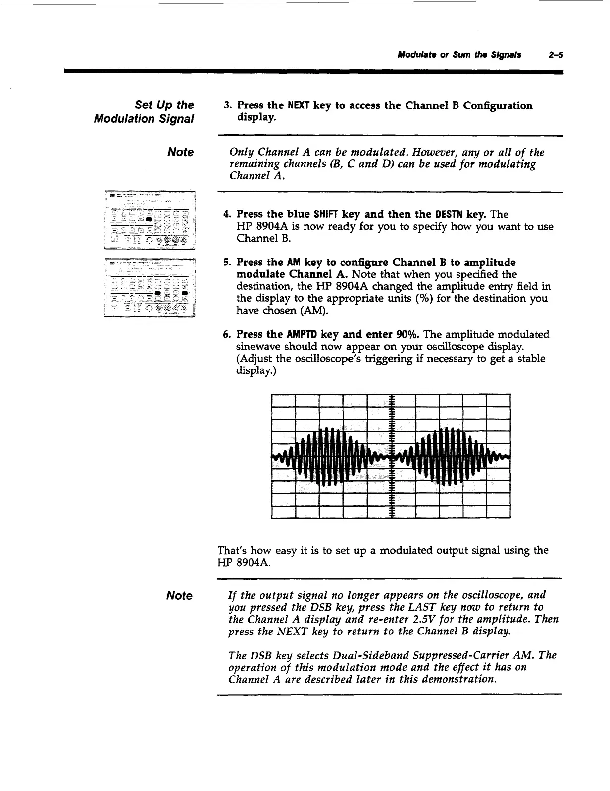
6.
Press the
AMPTD
key and enter
90%.
The amplitude modulated
sinewave should now appear
on
your oscilloscope display.
(Adjust the oscilloscope’s triggering
if
necessary to get
a
stable
display.)
f
I
I
I
1
s
I
I
I
I
1
I
I
I
I I
v
i
I
f
I
I
I
I
f
1
3
e
I
I
I
1
That’s how easy it is to set up a modulated output signal using the
HP
8904A.
If
the output signal
no
longer appears
on
the oscilloscope, and
you pressed the DSB key, press the
LAST
key
now
to return to
the Channel
A
display and re-enter
2.5V
for
the
amplitude. Then
press the NEXT key to return to the Channel B display.
The DSB key selects Dual-Sideband Suppressed-Carrier
AM.
The
operation
of
this modulation mode and the effect
it
has
on
Channel
A
are described later in this demonstration.
Artisan Technology Group - Quality Instrumentation ... Guaranteed | (888) 88-SOURCE | www.artisantg.com