Theory
of
Operation 2-27
One or two additional lOP boards can be added. Each
is
connected by a 50-conductor ribbon cable
to a connector mounted on the computer rear panel. The ribbon cable provides the
lOP bus from
the boards to the connector.
A
97098A
I/O
Expander can be connected to each additional lOP via the rear panel connector.
Each
I/O
expander provides eight
I/O
slots with signal buffering and power supplies. The select
code configuration at the
I/O
backplane
is
unaffected by additional lOPs. Select codes 0-6 are
assigned to the
I/O
backplane; select code 7
is
assigned to the system control module; select codes
8-15 are assigned to the
first
additional lOP; select codes 16-23 are assigned to the second
additional
lOP.
System Control Module
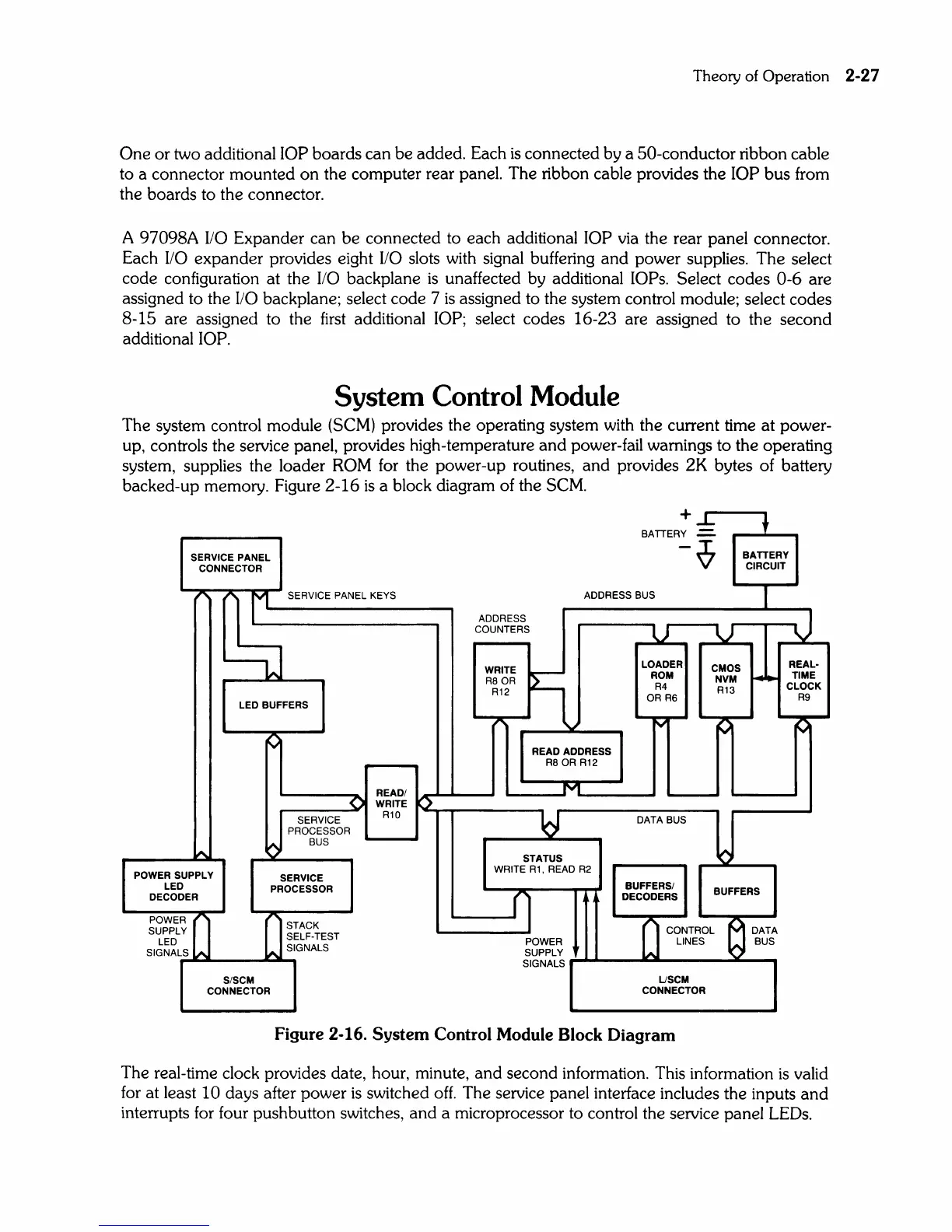
The system control module
(SCM)
provides the operating system with the current time at power-
up, controls the service panel, provides high-temperature and power-fail warnings to the operating
system, supplies the loader
ROM
for
the power-up routines, and provides 2K bytes of battery
backed-up memory. Figure 2-16
is
a block diagram of the
SCM.
SERVICE
PANEL
CONNECTOR
+...L.
BATTERY
.::.
-~
ADDRESS BUS
BATTERY
CIRCUIT
~
t'
r'--_S_ER_V_IC_E_P_AN_E_L_K_EY_S
__
__
ADDRESS
COUNTERS
------u----u--~~\J
POWER SUPPLY
LED
DECODER
g
LED BUFFERS
WRITE
f1
R8 OR
R12
-.,.""-~,,,
READ
ADDRESS
R8 OR R12
LOADER
ROM
R4
OR R6
READ/IAr""
.........
----'
_____
M
____
__
r-----...a()"I
WRITE
P~~""'-
___
__
~
SERVICE R10 L . .I
PROCESSOR Q
BUS
STATUS
WRITE R1, READ R2
SERVICE
PROCESSOR
DATA BUS
BUFFERS/
DECODERS
REAL·
CMOS
L.........
TIME
NVM
r-
~
CLOCK
R13 R9
BUFFERS
;~~~
I~I
II
~~~~-~EST
SIGNALr"S
...
~..-.
__
...
,,~S
...
IGNALS
CONTROL
"""I)
DATA
POWER LINES BUS
SUPPLY
S/SCM
CONNECTOR
SIGNALS
.....
---
.....
-------
......
USCM
CONNECTOR
Figure 2-16.
System
Control Module Block
Diagram
The real-time clock provides date, hour, minute, and second information. This information
is
valid
for
at least 10 days after power
is
switched
off.
The service panel interface includes the inputs and
interrupts
for
four pushbutton switches, and a microprocessor to control the service panel
LEOs.