Theory of Operation
Chapter
2
Introduction
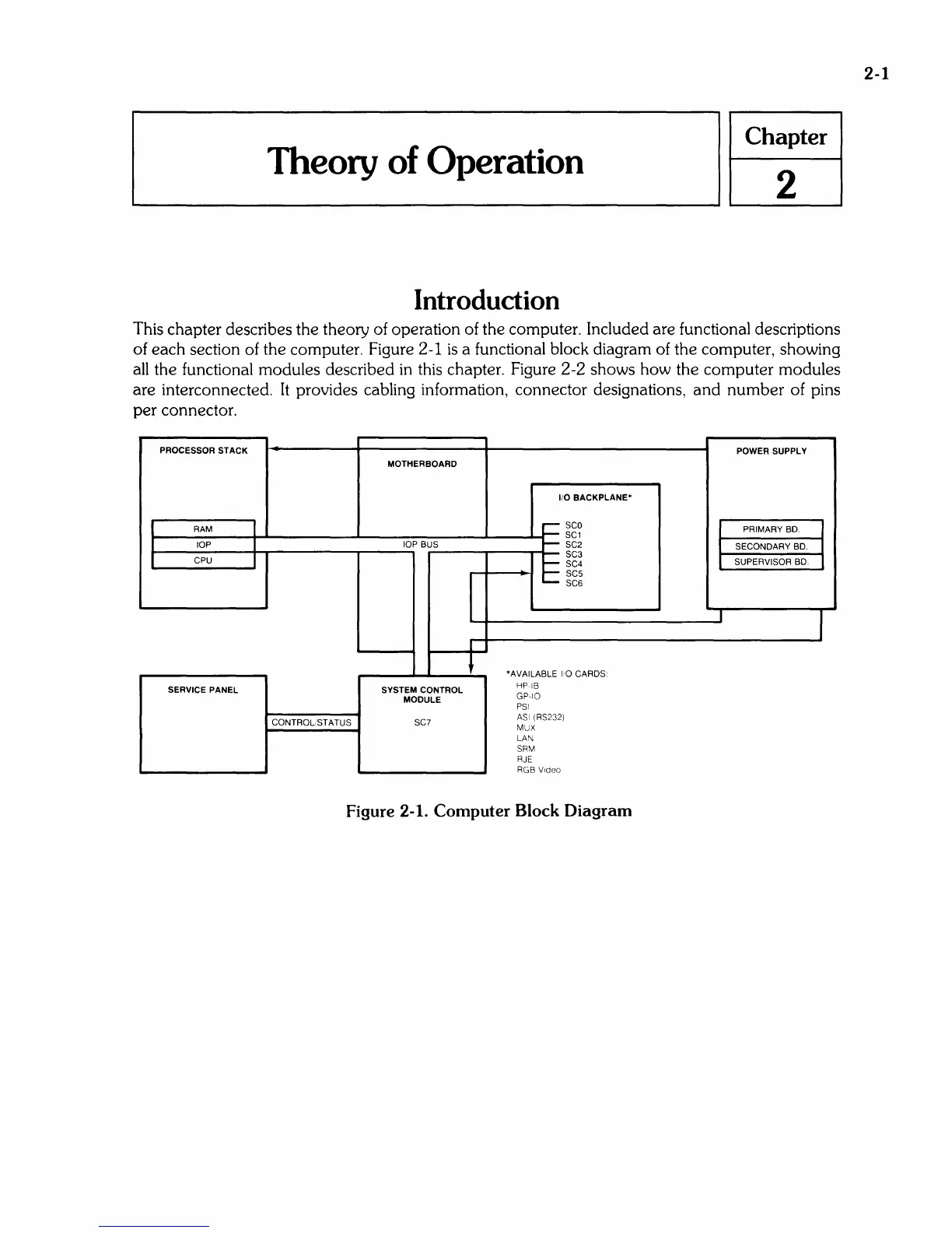
This chapter describes the theory of operation of the computer. Included are functional descriptions
of each section of the computer. Figure
2-1
is
a functional block diagram of the computer, showing
all the functional modules described
in
this
chapter. Figure
2-2
shows how the computer modules
are interconnected. It provides cabling information, connector deSignations, and number of pins
per connector.
PROCESSOR STACK
POWER SUPPLY
MOTHERBOARD
1/0 BACKPLANE"
RAM
~
sca
PRIMARY BD.
~
SC1
lOP
lOP BUS
~
SC2
SECONDARY
BD.
CPU
SC3
~
SC4
SUPERVISOR
BD.
~
SC5
--
SC6
I
1
*AVAILABLE
10
CARDS
SERVICE
PANEL SYSTEM CONTROL
Hp·IB
MODULE
GP·IO
PSI
CONTROL STATUS SC7
ASI
(RS232)
MUX
LAN
SRM
RJE
RGB
Video
Figure 2-1. Computer Block Diagram
2-1