15
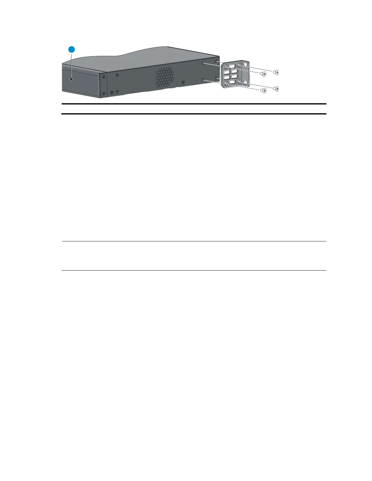
Figure 16 Rear mounting position (A5120-24G-PoE+ SI/A5120-24G-PPoE+ SI/A5120-48G SI)
Rack-mounting procedure
This task requires two persons. To mount the switch in a rack:
1. Wear an ESD-preventive wrist strap and make sure it makes good skin contact and is properly
grounded.
2. Check that the rack is properly grounded and can support the weight of the switch chassis and all
its accessories.
3. Check that the mounting brackets have been securely attached to the switch chassis.
4. Install cage nuts (user-supplied) in the mounting holes in the rack posts.
5. One person holds the switch chassis and aligns the oval holes in the brackets with the mounting
holes in the rack posts, and the other person fastens the mounting brackets with M6 screws (user-
supplied) to the rack, as shown in Figure 17 or Figure 18.
NOTE:
If a rack shelf is available, you can put the switch on the rack shelf, slide the switch to an appropriate
location, and attach the switch to the rack with the mounting brackets.

 Loading...


