EasyManuals Logo

HP A5120 EI Series Installation Guide

HP A5120 EI Series
91 pages
To Next Page IconTo Next Page
To Previous Page IconTo Previous Page
Page #25 background imageLoading...
Page #25 background image
20
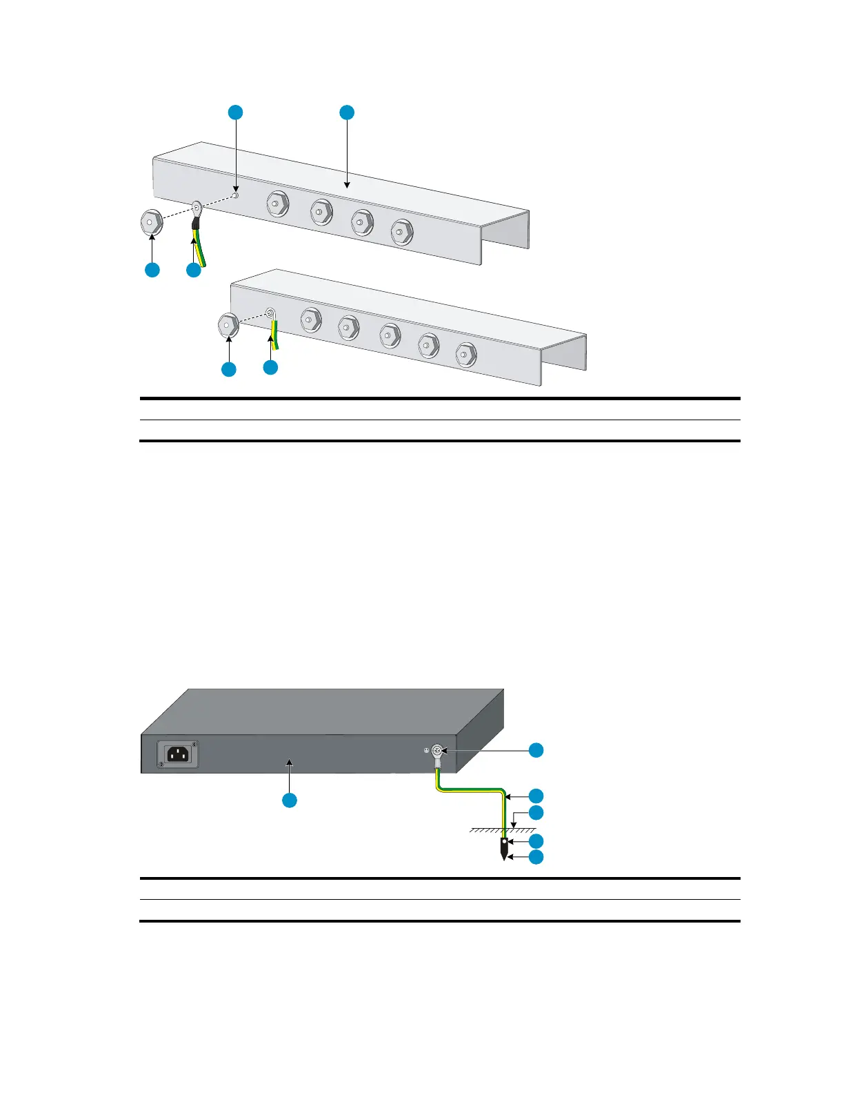
Figure 21 Connecting the grounding cable to a grounding strip
(A)
(B)
1 2
3
4
3
4
(1) Grounding post
(2) Grounding strip
(3) Grounding cable
(4) Hex nut
Grounding to a buried grounding conductor
If the installation site has no grounding strips, but earth ground is available, hammer a 0.5 m (1.64 ft) or
longer angle iron or steel tube into the earth ground to serve as a grounding conductor, as shown in
Figure 22.
The dimensions of the angle iron must be at least 50 × 50 × 5 mm (1.97 × 1.97 × 0.20 in). The steel
tube must be zinc-coated and its wall thickness must be at least 3.5 mm (0.14 in).
Weld the yellow-green grounding cable to the angel iron or steel tube, and treat the joint for corrosion
protection.
Figure 22 Ground the switch by burying the grounding conductor into the earth ground
1
2
3
4
5
6
(1) Grounding screw
(2) Grounding cable
(3) Earth
(4) Joint
(5) Grounding conductor
(6) Chassis rear panel

Table of Contents

Other manuals for HP A5120 EI Series

Questions and Answers:

Question and Answer IconNeed help?

Do you have a question about the HP A5120 EI Series and is the answer not in the manual?

HP A5120 EI Series Specifications

General IconGeneral
Uplink Ports4 x SFP
StackingNo
ManagementCLI, Web, SNMP
Routing ProtocolsRIP, OSPF
Power SupplyAC
MAC Address Table Size16K
Dimensions440 x 430 x 44 mm
Operating Temperature0°C to 45°C
Operating Humidity10% to 90% non-condensing
ModelHP A5120-24G EI Switch (JG234A)
VLANs4094

Related product manuals