EasyManuals Logo

HP A5120 EI Series Installation Guide

HP A5120 EI Series
91 pages
To Next Page IconTo Next Page
To Previous Page IconTo Previous Page
Page #61 background imageLoading...
Page #61 background image
56
A5120-24G-PoE+ EI (2 slots)/A5120-24G-PoE+ EI TAA (2
slots)
The A5120-24G-PoE+ EI (2 slots) and A5120-24G-PoE+ EI TAA (2 slots) switches come with the expansion
interface card slots covered by filler panels.
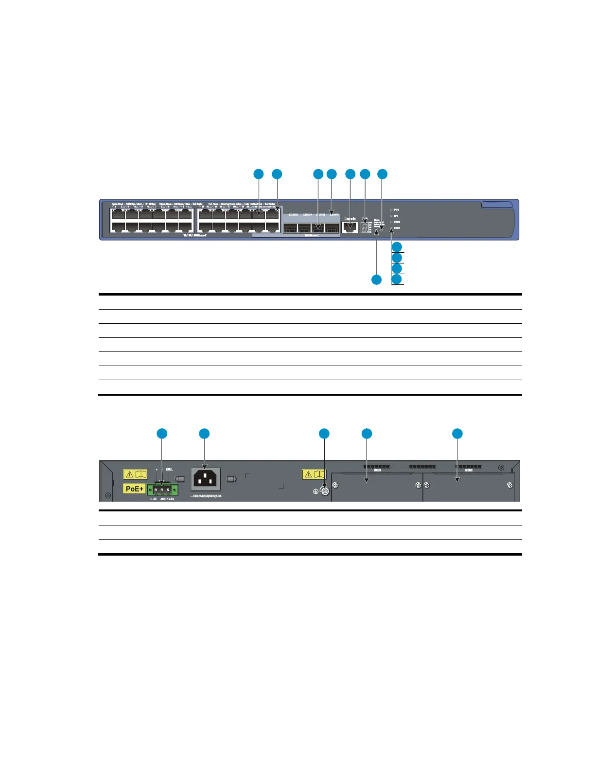
Figure 56 Front panel
1 2 3 4 5 6 7
8
9
10
11
12
(1) 10/100/1000Base-T auto-sensing Ethernet port
(2) 10/100/1000Base-T Ethernet port LED
(3) 1000Base-X SFP port
(4) 1000Base-X SFP port LED
(5) Console port
(6) Seven-segment LED (Unit)
(7) Port mode LED (Mode)
(8) System status LED (PWR)
(9) RPS status LED (RPS)
(10) Interface card 1 status LED (MOD1)
(11) Interface card 2 status LED (MOD2)
(12) Port LED mode switching button
Figure 57 Rear panel
1 2 3 4 5
(1) RPS receptacle
(2) AC-input power receptacle
(3) Grounding screw
(4) Interface card slot 1 (MOD1)
(5) Interface card slot 2 (MOD2)

Table of Contents

Other manuals for HP A5120 EI Series

Questions and Answers:

Question and Answer IconNeed help?

Do you have a question about the HP A5120 EI Series and is the answer not in the manual?

HP A5120 EI Series Specifications

General IconGeneral
Uplink Ports4 x SFP
StackingNo
ManagementCLI, Web, SNMP
Routing ProtocolsRIP, OSPF
Power SupplyAC
MAC Address Table Size16K
Dimensions440 x 430 x 44 mm
Operating Temperature0°C to 45°C
Operating Humidity10% to 90% non-condensing
ModelHP A5120-24G EI Switch (JG234A)
VLANs4094

Related product manuals