47
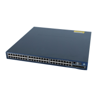
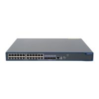
On the A5120-24G-PoE+ SI switch, look at the power LED and the RPS status LED of the switch. For
more information, see "LEDs (for the A5120 SI switches)."
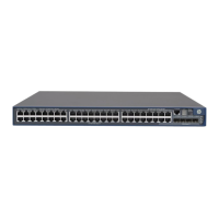
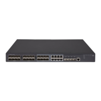
On any other A5120 SI switch, look at the power LED of the switch. For more information, see "LEDs
(for the A5120 SI switches)."
NOTE:
In the following subsections, the system status LED refers collectively to both the system status LED on
an A5120 EI switch and the power LED on an A5120 SI switch.
AC input
If the system status LED is off, an AC input failure has occurred. Check the following:
The AC power cord is securely connected to the switch, and the AC-input power receptacle on the
switch and the connected AC power outlet are in good condition.
The external AC power system is working correctly.
The operating temperature of the switch is in the normal range, and the power module has good
ventilation. Over-heating can cause the power module to stop working and enter the protection
state.
RPS DC input
If the system status LED or RPS status LED is off, an RPS input failure has occurred. Check the following:
The switch is securely connected to the RPS.
The RPS is working correctly.
The operating temperature of the switch is in the normal range, and the power supply has good
ventilation. Overheating can cause the power supply to stop working and enter the protection state).
Concurrent RPS and AC inputs
1. If the system status LED is off, the AC power supply and the RPS both have an input failure.
Check the following:
The AC power cord is securely connected to the switch, and the AC-input power receptacle on
the switch and the connected AC power outlet are in good condition.
The external AC power system is working correctly.
The switch is securely connected to the RPS.
The RPS is working correctly.
The operating temperature of the switch is in the normal range, and the power supply has good
ventilation. Overheating can cause the power supply to stop working and enter the protection
state.
2. If the system status LED is on but the RPS status LED is steady yellow, an AC input failure has
occurred.
Check the following:
The AC power cord is securely connected to the switch, and the AC-input power receptacle on
the switch and the connected AC power outlet are in good condition.
The external AC power system is working correctly.
3. If the system status LED is on but the RPS status LED is off, an RPS input failure has occurred.
Check the following:
 Loading...

