Installing Hardware Options
Identifying System Board Components
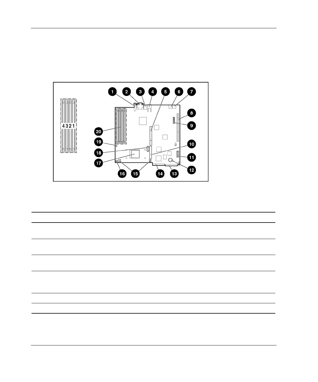
Use the following figure and table to identify the system board connectors and
components for option installation or service events.
Figure 3-4: Identifying system board components
Table 3-1: System Board Connectors and Components
Location Component Location Component
1 Unit Identification (UID)
LED/button
7 USB connector 2
2 Serial (top) and video (bottom)
connectors
8 64-bit 33-MHz PCI riser board
assembly connector
3 Mouse (top) and keyboard
(bottom) connectors
9 System configuration switch
(SW1)
4 RJ-45 fast Ethernet connectors
for NIC 1 (bottom) and NIC 2
(top)
10 ATA controller (secondary)
5 Slotless SCSI module slot 11 Power connector
6 USB connector 1 12 System battery
continued
3-6 HP ProLiant DL320 Generation 2 Server Setup and Installation Guide
HP CONFIDENTIAL
Writer: Anna Roberts File Name: d-ch3 Installing Hardware Options.doc
Codename: MoonStar Part Number: 293166-002 Last Saved On: 1/31/03 11:16 AM

 Loading...