EasyManuals Logo

HP dx7500 - Microtower PC User Manual

HP dx7500 - Microtower PC
200 pages
To Next Page IconTo Next Page
To Previous Page IconTo Previous Page
Page #134 background imageLoading...
Page #134 background image
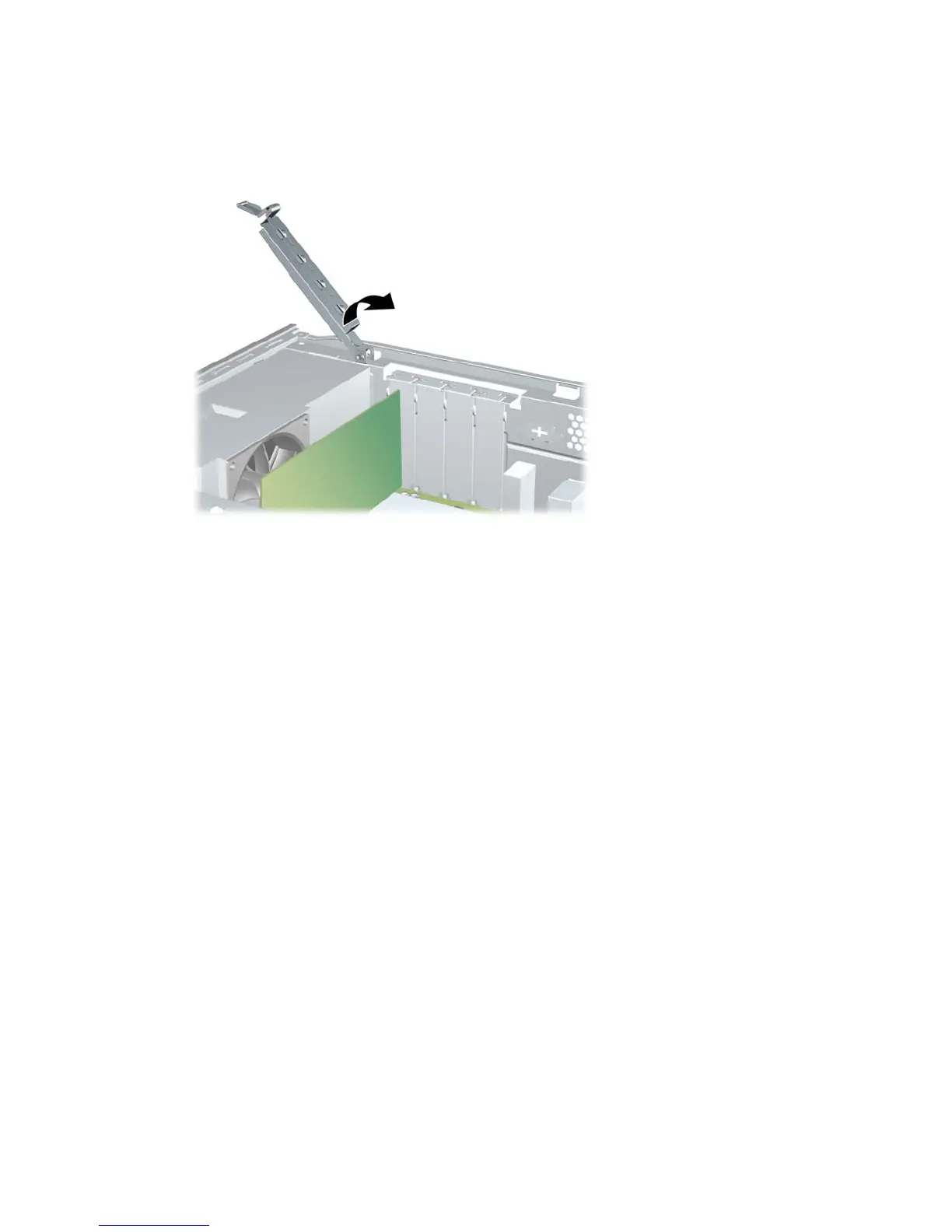
9. While holding the expansion card bracket against the chassis, rotate the slot cover lock over the
expansion card brackets and slot covers. Push the slot cover lock down to latch it and secure the
card brackets.
Figure 8-39 Closing the Slot Cover Lock
10. Connect external cables to the installed card, if needed. Connect internal cables to the system
board, if needed.
11. Replace the computer access panel.
12. Reconnect the power cord and any external devices, then turn on the computer.
13. Lock any security devices that were disengaged when the access panel was removed.
14. Reconfigure the computer, if necessary. Refer to the Computer Setup (F10) Utility Guide for
instructions on using Computer Setup.
124 Chapter 8 Removal and Replacement Procedures Small Form Factor (SFF) Chassis

Table of Contents

Other manuals for HP dx7500 - Microtower PC

Questions and Answers:

Question and Answer IconNeed help?

Do you have a question about the HP dx7500 - Microtower PC and is the answer not in the manual?

HP dx7500 - Microtower PC Specifications

General IconGeneral
MemoryUp to 8 GB DDR2 SDRAM
Form FactorMicrotower
Power Supply300W
ProcessorIntel Core 2 Duo, Intel Pentium Dual-Core, Intel Celeron
StorageSATA hard drives up to 500 GB
Optical DriveDVD-ROM or DVD+/-RW
GraphicsIntegrated Intel Graphics Media Accelerator 3100, Optional discrete graphics cards
AudioIntegrated High Definition Audio
NetworkIntegrated Gigabit Ethernet
Expansion Slots1 PCI Express x16, 2 PCI Express x1, 1 PCI
PortsUSB 2.0, serial, parallel, VGA, audio in/out
Operating SystemWindows Vista Business, Windows XP Professional, FreeDOS
WeightApprox. 22 lbs (10 kg)

Related product manuals