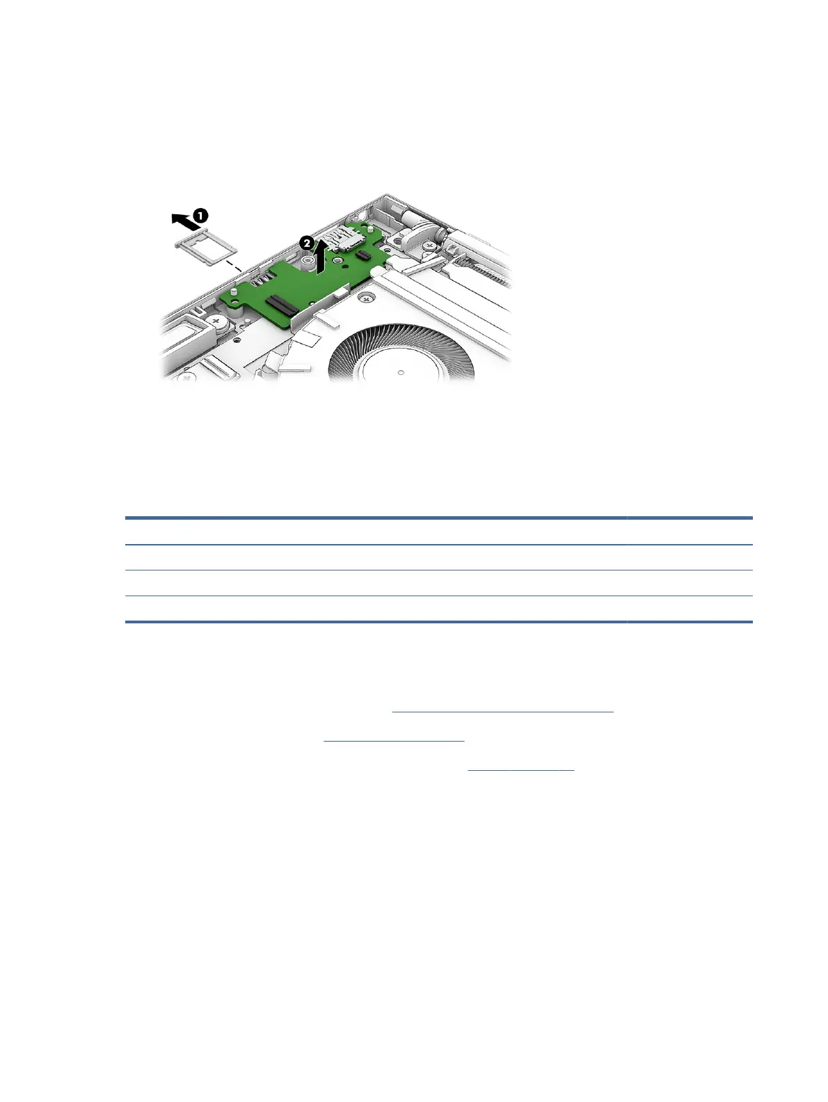
7. Remove the connector board (2) from the computer.
To install the connector board, reverse the removal procedure.
Fan
To remove the fan, use this procedure and illustration.
Table 5-9
Fan descriptions and part numbers
Description Spare part number
Fan (includes captive screws and cable):
For use with system boards equipped with a 28 W processor N09036-001
For use with system boards equipped with a 15 W processor N09035-001
Before removing the fan, follow these steps:
1. Prepare the computer for disassembly (see Preparation for disassembly on page 39).
2. Remove the bottom cover (see Bottom cover on page 39).
3. Disconnect the battery cable from the system board (see Battery on page 41).
Remove the fan:
1. Disconnect the fan cable (1) from the system board.
2. Release the WWAN antenna cables from the retention clips (2) that are built into the fan.
3. Loosen the three captive Phillips screws (3) that secure the fan to the computer.
54
Chapter 5Removal and replacement procedures for authorized service provider parts
 Loading...