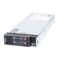
Server Blade Component Identification
Table 1-2: ProLiant BL30p Server Blade Front Panel LEDs, Button, and
Port
continued
Item LED/Button
Description
Status
3 NIC 1 LED*
4 NIC 2 LED*
Green = Linked to network
Green flashing = Network activity
Off = No activity
5 Hard Drive Activity
LED
Green/Flashing = Activity
Off = No activity
6 Power LED/button Green = On
Amber = Standby (power available)
Off = Unit off
7 I/O port** -
*Actual NIC numeration depends on several factors, including the operating
system installed on the server.
**The I/O port is used with the local I/O cable to perform some server blade
configuration and diagnostic procedures.
System Maintenance Switch
The system maintenance switch (SW1) is an 8-position switch that implements
protection and override functions. The default position is off. For the proper system
maintenance switch settings, refer to Table 1-3 or refer to the label attached to the
server blade.
HP ProLiant BL30p Server Blade Setup and Installation Guide 1-5
 Loading...