HP StorageWorks SN6000 Fibre Channel Switch Installation and Reference Guide 57
Power Supply Diagnostics
The same model power supply is used for the SN6000 Single Power Supply Fibre Channel Switch and the
SN6000 Dual Power Supply Fibre Channel Switch. The power supply is replaceable on both SN6000
Fibre Channel Switches, and is hot-swappable on the SN6000 Dual Power Supply Fibre Channel Switch.
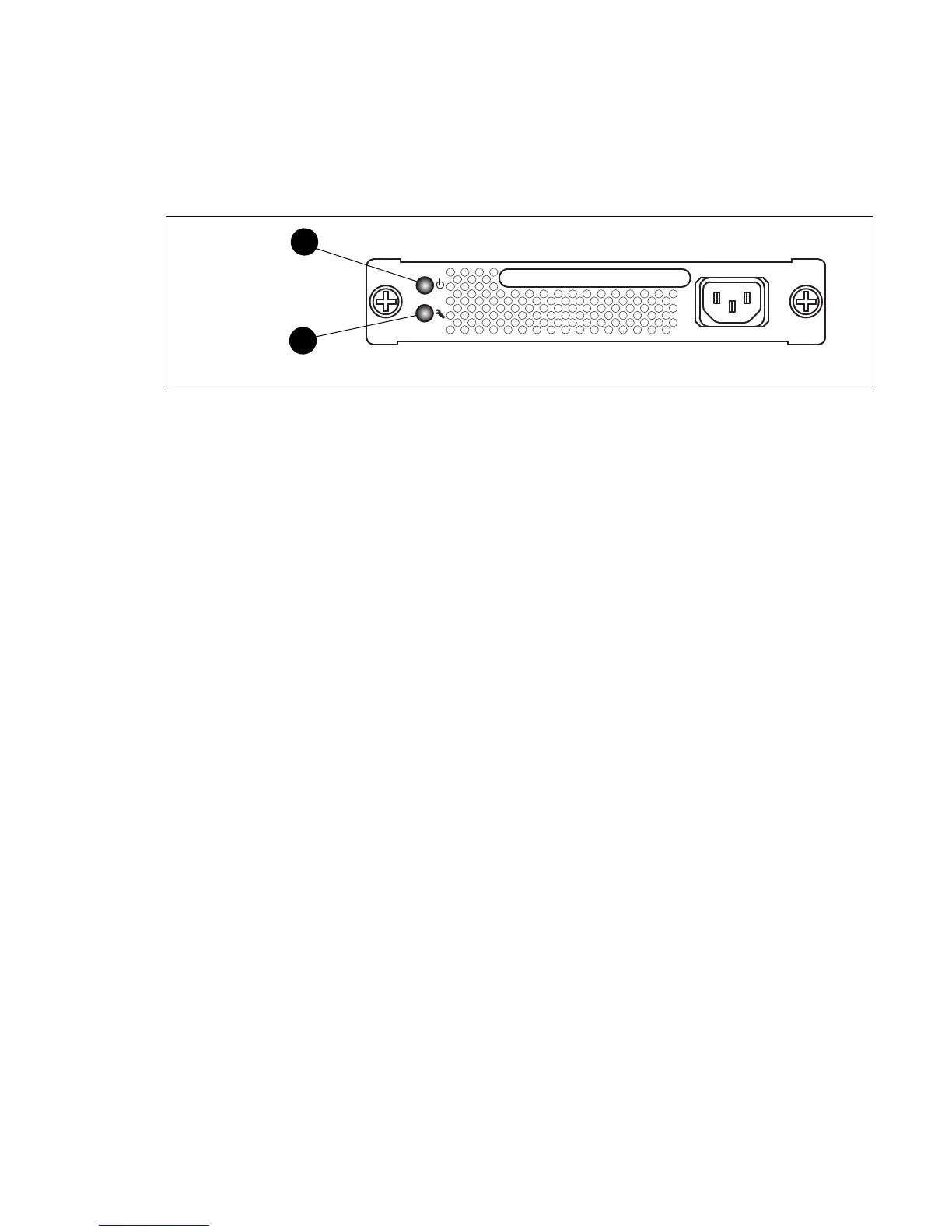
The power supply has a Status LED (Green) and a Fault LED (Amber) as shown in Figure 22. Under normal
operating conditions, the Power Supply Status LED is illuminated and the Power Supply Fault LED is
extinguished.
Figure 22 SN6000 Fibre Channel Switch power supply LEDs
Consider the following indications:
• All power supply LEDs are normal, yet the System Fault LED is illuminated and the Heartbeat LED does
not show a blink pattern. This means that the two power supplies have different air flow directions.
Replace the power supply with the incorrect air flow direction with a power supply that has the correct
air flow direction. Air flow direction is marked on the power supply part number label. See ”Power
supply removal and replacement” (page 61).
• Power Supply Fault LED is illuminated. This means that the power supply is failing or has failed.
Replace the power supply with a power supply that has the same air flow direction. Air flow direction is
indicated on the power supply part number label. See ”Power supply removal and
replacement” (page 61).
Recovering a switch using maintenance mode
A switch can become inoperable or unmanageable for the following reasons:
• Firmware becomes corrupt
• IP address is lost
• Switch configuration becomes corrupt
• Password is forgotten
In these specific cases, you can recover the switch using maintenance mode. Maintenance mode
temporarily returns the switch IP address to 10.0.0.1 and provides opportunities to do the following:
• Exiting the maintenance menu (option 0), page 58
• Unpacking a firmware image file in maintenance mode (option 1), page 58
• Resetting the network configuration in maintenance mode (option 2), page 59
• Resetting user accounts in maintenance mode (option 3), page 59
• Copying log files in maintenance mode (option 4), page 59
• Removing the switch configuration in maintenance mode (option 5), page 59
• Remaking the file system in maintenance mode (option 6), page 59
• Resetting the switch in maintenance mode (option 7), page 59
• Updating the boot loader in maintenance mode (option 8), page 59
1 Power supply status LED 2 Power supply fault LED
 Loading...