Installing the switch
Installation overview
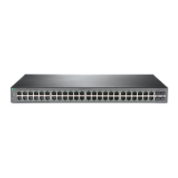
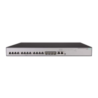
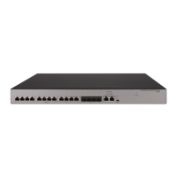
The 1920S Switches are easy to install. They come with an accessory kit that includes the brackets for
mounting the switches in a standard 19-inch telco rack, in an equipment cabinet, and with rubber feet that
can be attached so the switches can be securely located on a horizontal surface. The brackets are
designed to allow mounting of the switches in a variety of locations and orientations. This chapter shows
how to install the switches.
Fan-free design
NOTE:
The switches covered by this guide have a fan-free design, making them quiet for office
deployments. A warmer than normal enclosure is a standard state of operation for a fan-free switch.
Although the top of the switch enclosure may feel warm to the touch, it has no effect on functionality
or performance of the product.
Included parts
The following components ship with an 1920S Switch:
Documentation kit
• Quick Setup Guide
• Safety and Regulatory information
• Software License, Warranty, and Support information
• Accessory kits:
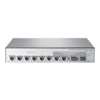
1920S 8G and 1920S 8G PPoE+ Switch
Kit number 5066-2232
• two rack mounting brackets
• eight 8-mm M4 screws to attach the mounting
brackets to the switch
• four 5/8-inch number 12-24 screws to attach the
switch to a rack
• four rubber feet
Kit number 5066-0621
• three 3/4” (20-mm M4) screws for wall and
under-table mounting
• three wall anchors
• cable tie for power cord
Installing the switch 13
 Loading...
