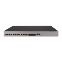
Cable Diagram
Connector A Connector B
White/Orange
1000Base-T
Straight-through cable
1 2 3 4 5 6 7 8
1 2 3 4 5 6 7 8
Orange/White
White/green
green/White
blue/white
white/blue
white/brown
brown/white
NOTE:
• Pins 1 and 2 on connector “A” must be wired as a twisted pair to pins 1 and 2 on connector “B”.
• Pins 3 and 6 on connector “A” must be wired as a twisted pair to pins 3 and 6 on connector “B”.
• Pins 4 and 5 on connector “A” must be wired as a twisted pair to pins 4 and 5 on connector “B”.
• Pins 7 and 8 on connector “A” must be wired as a twisted pair to pins 7 and 8 on connector “B”.
Pin Assignments
For 1000BASE-T operation, all four pairs of wires are used for both transmit and receive.
44 Cable Diagram
 Loading...