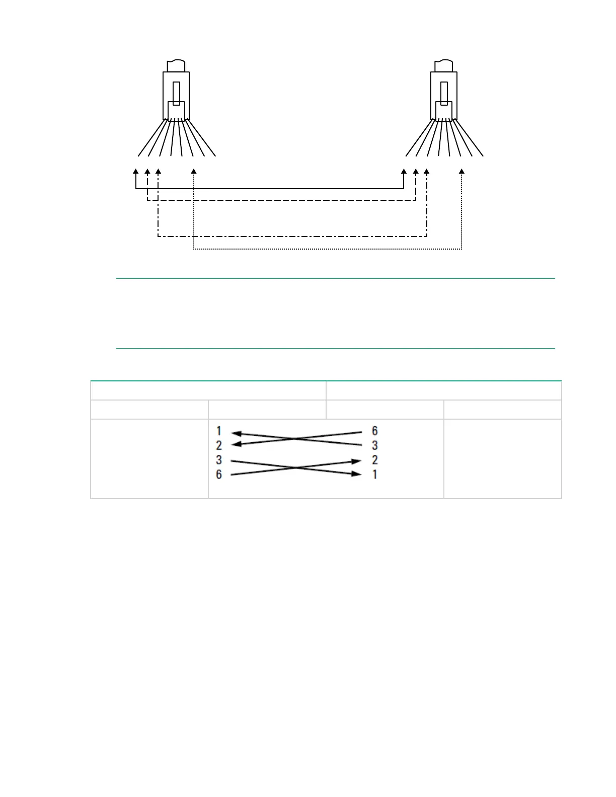
EasyManuals Logo

HPE OfficeConnect 1920S Series User Manual

HPE OfficeConnect 1920S Series
45 pages
To Next Page IconTo Next Page
To Previous Page IconTo Previous Page
Page #43 background imageLoading...
Page #43 background image
Cable Diagram
Connector A Connector B
Crossover cable
white/orange
orange/white
white/green
green/white
1 2 3 4 5 6 7 8
1 2 3 4 5 6 7 8
NOTE:
Pins 1 and 2 on connector “A” must be wired as a twisted pair to pins 3 and 6 on connector “B”.
Pins 3 and 6 on connector “A” must be wired as a twisted pair to pins 1 and 2 on connector “B”.
Pins 4, 5, 7, and 8 are not used in this application, although they may be wired in the cable.
Pin Assignments
Switch End (MDI-X) Hub or Switch Port, or Other MDI-X Port End
Signal Pins Pins Signal
receive +
receive -
transmit +
transmit -
transmit -
transmit +
receive -
receive +
Straight-Through Twisted-Pair Cable for 1000 Mbps Network Connections
1000BASE-T connections require that all four pairs of wires be connected.
Cable Diagram 43

Table of Contents

Questions and Answers:

Question and Answer IconNeed help?

Do you have a question about the HPE OfficeConnect 1920S Series and is the answer not in the manual?

HPE OfficeConnect 1920S Series Specifications

General IconGeneral
ModelHPE OfficeConnect 1920S Series
PoE+ SupportYes (on select models)
ManagementWeb-based GUI, SNMP
LayerLayer 2
MountingRack-mountable
Power SupplyInternal
Forwarding RateUp to 95.2 Mpps
Input Voltage100-240VAC
Power ConsumptionVaries by model
Operating Temperature0°C to 40°C (32°F to 104°F)
LatencyVaries by model
DimensionsVaries by model
WeightVaries by model
CertificationsCE, FCC, RoHS
Ports8, 24, or 48 ports

Related product manuals