Interfaces
63
User Manual
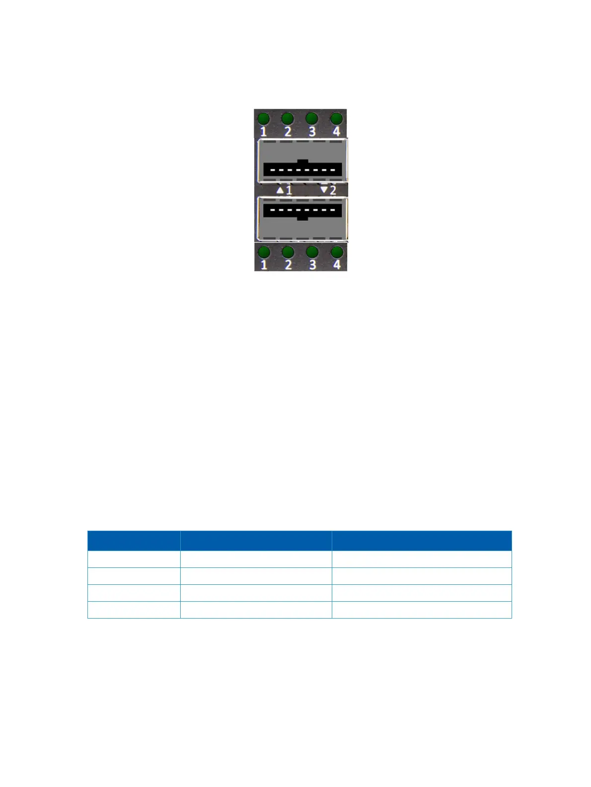
Figure 63: SN2100M Port LEDs
In the SN2410M/SN2410bM systems, the status of each pair of adjacent QSFP28 ports is indi-
cated by four LEDs, as shown in the picture above:
• While the bottom LEDs signify the port status in regular condition, the upper LEDs
operate only when the port is split.
• When one port is split to two, a connection of 100GbE can be utilized in its adjacent
port.
• When one port is split to four, it adjacent port is canceled.
• If the ports run at a 100GbE/40GbE speed each, the two lower LEDs (2 and 4) will light
green.
• If the ports run at a 50GbE speed each, the left LEDs (1 and 2) will light green for the
upper port, and the right LEDs (3 and 4) will light green for the lower port.
• If the ports run at a 25GbE/10GbE speed each, all LEDs may light green, according to
the selected lane.
Table 22 - Port LEDs in Ethernet System Mode
3.3 Inventory Information
The system’s inventory parameters (such as Serial Number, Part Number, GUID and MAC
address) can be extracted from the inventory pull-out tab on the lower right side of the front
panel. In some systems, there is no pull-out tab, and the information is provided on labels in sev
-
eral locations.
LED Behavior Description Action Required
Off Link is down. Check the cable
Solid Green Link is up with no traffic. N/A
Flashing Green Link is up with traffic. N/A
Flashing Amber A problem with the link. Check the cable, and replace it if needed.
 Loading...


