Shenzhen Hpmont Technology Co., Ltd Chapter 6 Function Introduction
HD20 Series Inverters User Manual ―91―
No. Name Description Range
factory setting
16, 17: Rserved.
18,19: Output frequency, reference frequency (- 1 times-1 times maximum output frequency).
F16.23 Analogue output AO1 gain 0.0
200.0
100.0%
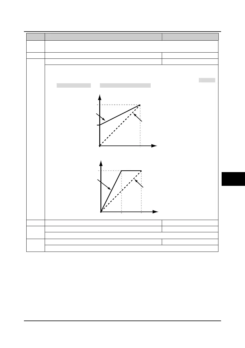
• This parameter is used to realise the proportional relation adjustment of AO1 analogue output.
• The formula is: Y=kX+b
• Y is actual output value, X is output value with ratio and gain not being adjusted, k is analogue
output gain (F16.23), b is analogue output bias (F16.22).
The relationship between analogue output and bias is shown as following figure.
The relationship between analogue output and gain is shown as following figure.
F16.24 Analogue output AO2 bias -100.0
100.0
0.0%
Refer to parameters F16.22 and F16.23.
DO2 maximum output pulse frequency
It defines the DO2 terminal allowable maximum output frequency.
0
10
F16.22=0
F16.22=50%
50%
100%
Value after regulating (V)
Value before regulating (V)
0
10
Value after regulating (V)
100%
F16.23=100%
F16.23=200%
5
Value before regulating (V)
6

 Loading...

