Shenzhen Hpmont Technology Co., Ltd Appendix B Communication Protocol
HD20 Series Inverters User Manual -151-
Appendix B Communication Protocol
1. Peripherals Support
HD20 series Inverters provide two RS485 communication interfaces which both use the standard
MODBUS communication protocol. By using the host computer (including communication
devices such as computer and PLC) the user can operate to read-write the inverter’s function
code, read the status parameters and write the control command etc. The inverter is in slave
mode when it is communicating.
2. Interfaces
1) Interface mode and pin definition
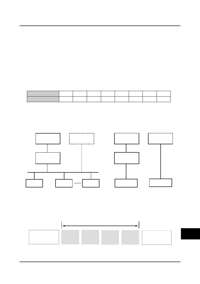
Definition of the RJ45 pin signal
PIN
1 2 3 4 5 6 7 8
SIGNAL
+5V 485+ +5V GND GND GND 485- Reserved
2) Communication mode
RS485 interface: asynchronous, semi-duplex.
Default: 8-N-2, 9600bps.
3. Network Mode
4. Protocol Format
The MODBUS protocol simultaneously supports RTU mode and ASCII mode, with corresponding
frame format as shown below:
PC master PLC master
RS232/RS485
switching module
HD20 HD20 HD20
Single-master and multi-slave
RS485
PC master
PLC master
RS232/RS485
switching module
HD20
Single-master and single-slave
RS485
HD20
Slave
address
Framehead(at least
3.5 character spacing)
Function
parameter
Data
Checking
Modbus dataframe
Frametail(at least
3.5 character spacing)
B

 Loading...

