Chapter 4 Electrical Installation Shenzhen Hpmont Technology Co., Ltd
―18― HD20 Series Inverters User Manual
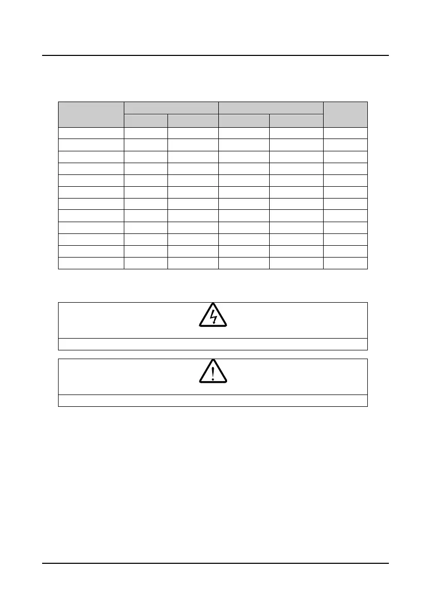
4.2 Selection of Main Circuit Peripheral Devices
Please refer to the Table 4-1 for the recommended specifications.
Table 4-1 HD20 series inverters I/O wiring specification
Model
Input Protection Main Circuit (mm
2
)
Control
Circuit (mm
2
)
MCCB (A) Contactor (A) Supply Cables Motor Cables
HD20-2S0P2G 16 10 1.0 1.0 ≥0.5
HD20-2S0P4G 16 10 1.0 1.0 ≥0.5
HD20-2D0P7G 16 10 1.5 1.5 ≥0.5
HD20-2D1P5G 20 16 2.5 1.5 ≥0.5
HD20-2D2P2G 32 20 4.0 2.5 ≥0.5
HD20-4T0P4G 10 10 1.0 1.0 ≥0.5
HD20-4T0P7G 10 10 1.0 1.0 ≥0.5
HD20-4T1P5G 16 10 1.0 1.0 ≥0.5
HD20-4T2P2G 16 10 1.5 1.5 ≥0.5
HD20-4T3P0G 25 16 2.5 2.5 ≥0.5
HD20-4T4P0G 25 16 2.5 2.5 ≥0.5
HD20-4T5P5G 32 25 4.0 4.0 ≥0.5
4.3 Power Terminals and Wiring
• The bare portions of the power cables must be bounded with insulation tapes.
• Ensure that AC supply voltage is the same as inverter’s rated input voltage.

 Loading...

