Chapter 6 Function Introduction Shenzhen Hpmont Technology Co., Ltd
―74― HD20 Series Inverters User Manual
6.2.11 Group F10 Motor 1 Vector Control Speed-loop Parameters
No. Name Description Range
factory setting
F10.00 Speed control proportional gain 1 of motor 1 0.1
200.0
20.0
Speed control integral time 1 of motor 1
F10.02 Speed control proportional gain 2 of motor 1 0.1
200.0
20.0
Speed control integral time 2 of motor 1
F10.04 Speed-loop PI switching frequency 1 of motor 1 0.00
50.00
10.00Hz
Speed-loop PI switching frequency 2 of motor 1
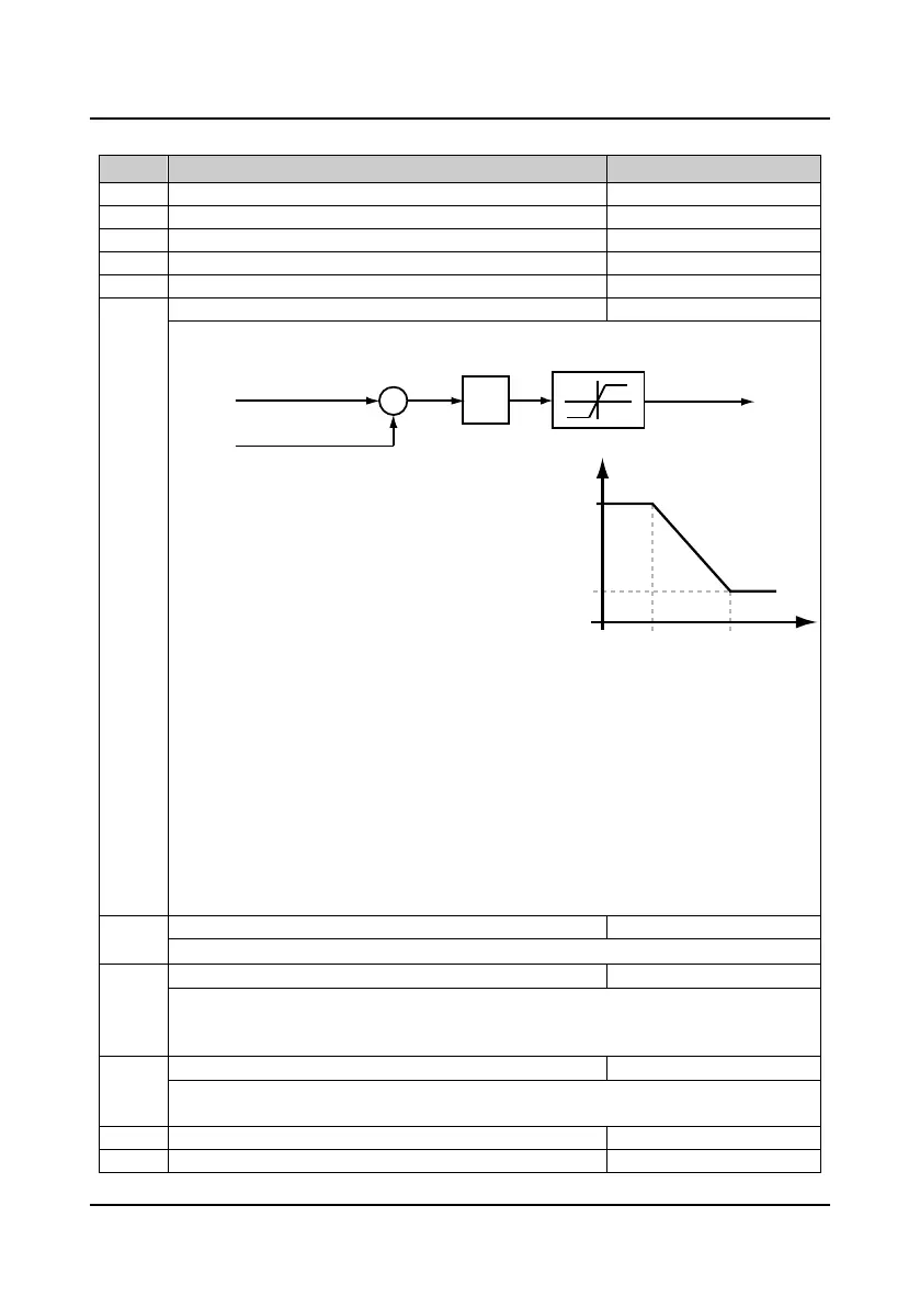
The parameters of F10.00-F10.05 and F10.07 comfirm the PID parameters of automatic speed
regulator (ASR). The structure of ASR is shown in figure.
As the right figure:
• When the inverter operates with frequency in a range
of 0-F10.04, the PI parameters of vector control are
F10.00 and F10.01;
• When the inverter operates with frequency above the
value of F10.05, the PI parameters of vector control
are F10.02 and F10.03;
• When the inverter operates with frequency in a range
of F10.04-F10.05, P is the linear interpolation
between F10.00 and F10.02, while I is the linear
interpolation between F10.01 and F10.03.
• The system’s response can be expedited through increasing the ASR proportional gain P, but
oscillation may occur if the value of P is too high.
• The system’s response can be expedited through increasing the ASR integral constant Ti, but
oscillation and high overshoot happen easily if the value of Ti is too high.
• If Ti =0, the integral function is disabled and the speed-loop works only as a proportional
controller.
• Generally, the proportional gain P should be adjusted firstly to the maximum on condition that the
system does not vibrate, and then the integral constant Ti should be adjusted to shorten the
response time without overshoot.
• It need increase proportional gain (P) and decrease integral constant (Ti), on condition that shorter
dynamic response time is required during low frequency operation.
F10.06 Speed-loop integral limitation of motor 1 0.0
200.0 (F08.02)
180.0%
It is used to limit the maximum value of the vector control speed-loop integral.
F10.07 Speed-loop differential time of motor 1 0.00
1.00
0.00s
It defines the vector control speed-loop differential time.
• Generally, it doesn’t need to set F10.07 except for expediting the dynamic response.
• There is not the speed-loop differential when F10.07 = 0.
F10.08 Speed-loop output filter time of motor 1 0.000
1.000
0.020s
It is used to filter the output of ASR regulator.
• When F10.08 = 0, the speed-loop filter is disabled.
F10.09 Reserved
Torque current
reference
Frequency command
+
-
Frequency feedback
PID
Error
Torque limit
F10.04 F10.05
F10.00 /
F10.01
F10.02 /
F10.03
0
Frequency
PI parameter

 Loading...

