Shenzhen Hpmont Technology Co., Ltd Chapter 6 Function Introduction
HD20 Series Inverters User Manual ―75―
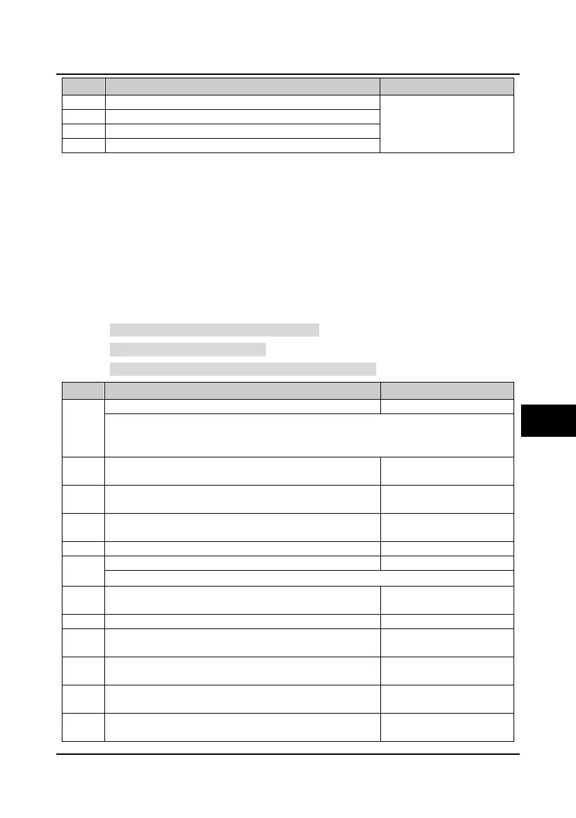
No. Name Description Range
factory setting
F10.11 Motor torque limitation when motor 1 is forward 0.0
200.0 (F08.02)
180.0%
Motor torque limitation when motor 1 is reverse
F10.13 Recreated torque limitation when motor 1 is forward
Recreated torque limitation when motor 1 is reverse
6.2.12 Group F11 Reserved
6.2.13 Group F12 Reserved
6.2.14 Group F13 Asynchronous Motor 2 Parameters
This group can be set as the second group of motor parameters and control parameters
corresponding to the first group parameters (motor 1). The concrete meaning refers the
corresponding parameters of motor 1 and achieves flexible switching between the 2 motors (refer
to multi-function input terminal No. 47 function).
Note:
Refer to Group F08 Asynchronous Motor 1 parameters for F13.01-F13.15.
Refer to Group F09 V/f Control parameters for F13.16-F13.34.
Refer to Group F10 Motor 1 Vector Control Speed-loop Parameters for F13.35-F13.49.
No. Name Description Range
factory setting
Control mode selection of motor 2
0: V/f control without PG.
1: Reserved.
2: Vector control without PG.
F13.01 Rated power of motor 2 0.2
11.0kW
dependent on
F13.02 Rated voltage of motor 2 0
999V
dependent on
inverter model
F13.03 Rated current of motor 2 0.01
99.99A
dependent on
F13.04 Rated frequency of motor 2 1.0
400.0
50.0Hz
F13.04 and F13.05 should be set in accordance with the parameters of motor nameplate.
F13.06 Power factor of motor 2 0.001
1.000
dependent on
F13.07 Parameter auto-tuning of motor 2 0
2
0
F13.08 Stator resistance of motor 2 0.00
99.99Ω
dependent on
F13.09 Rotor resistance of motor 2 0.00
99.99Ω
dependent on
inverter model
F13.10 Leakage inductance of motor 2 0
9999mH
dependent on
F13.11 Mutual inductance of motor 2 0
5000mH
dependent on
inverter model
6

 Loading...

