Chapter 6 Function Introduction Shenzhen Hpmont Technology Co., Ltd
―102― HD20 Series Inverters User Manual
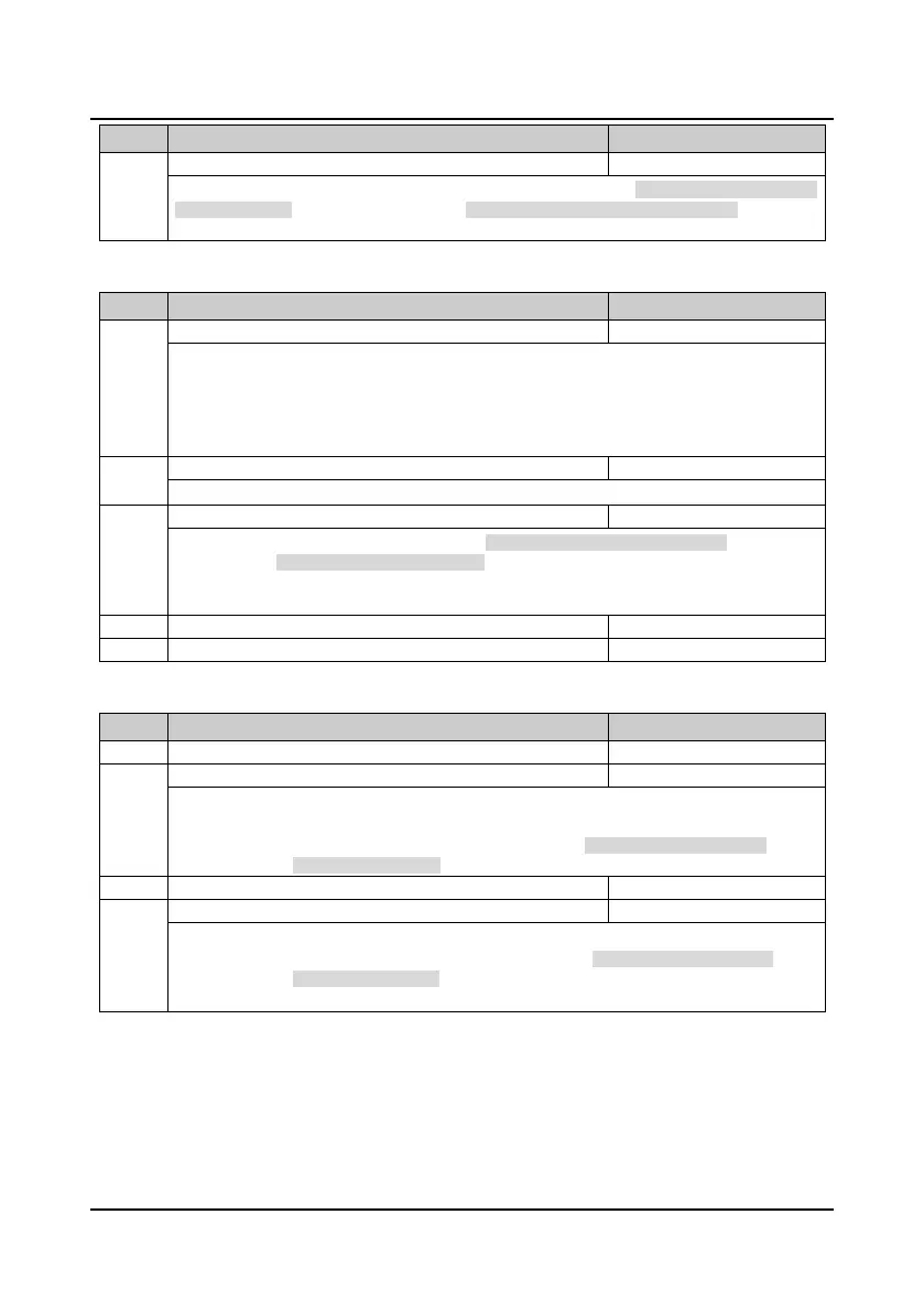
No. Name Description Range
factory setting
F20.02 Overload pre-alarm detection time 0.0
60.0
5.0s
F20.02 defines the time during which the inverter output current exceeds overload pre-alarm detection
threshold (F20.01). If the status remains after overload pre-alarm detection time (F20.02), the inverter
will output pre-alarm signal.
Inverter output load-loss detection fault (F20.03
F20.05)
No. Name Description Range
factory setting
F20.03 Inverter output load-loss detection 0
4
0
0: Disabled. It does not detect inverter output load-loss.
1: It is detecting all the time in running process, and then continues operation after detecting (alarm).
2: It detectes only at the same speed, and then continues operation after detecting (alarm).
3: It is detecting all the time in running process, and then cut off the output after detecting (fault).
4: It is detectes only at the same speed, and then cut off the output after detecting (fault).
F20.04 Inverter output load-loss detection threshold 0
100
30%
F20.04 defines the current threshold of load-loss. It is a percentage of the inverter’s rated current.
F20.05 Inverter output load-loss detection time 0.00
20.00
1.00s
If the inverter’s output current is smaller than the load-loss detection threshold (F20.04) beyond the
time defined by load-loss detection time (F20.05), the inverter will alarm inverter load-loss fault
(E0018).
• When F20.04 or F20.05 is set to 0, the inverter will not detect load loss fault.
F20.06 Reserved
Input and output phase loss fault (F20.08
F20.11)
No. Name Description Range
factory setting
F20.08 Input phase loss detection reference 0
50
30%
Input phase loss detection time
F20.08 value is a percentage of the inverter’s rated voltage.
• When F20.08 is set to 0, the inverter will not detect input phase loss fault.
When the inverter detects certain input voltage not hit the preset detection reference (F20.08) and
exceed the preset detection time (F20.09), the inverter will perform input phase loss alarm (E0015).
Output phase loss detection reference
F20.11 Output phase loss detection time 0.00
20.00
3.00 s
F20.10 value is a percentage of the inverter’s rated current.
When the inverter detects certain output current not hit the preset detection reference (F20.10) and
exceed the preset detection time (F20.11), the inverter will perform output phase loss alarm (E0016).
• When F20.10 or F20.11 is set to 0, the inverter will not detect output phase loss fault.

 Loading...

