Appendix B Communication Protocol Shenzhen Hpmont Technology Co., Ltd
―158― HD20 Series Inverters User Manual
Characteristics (Bit) Value Definition
Bit15-Bit13 Manufacturer reserved
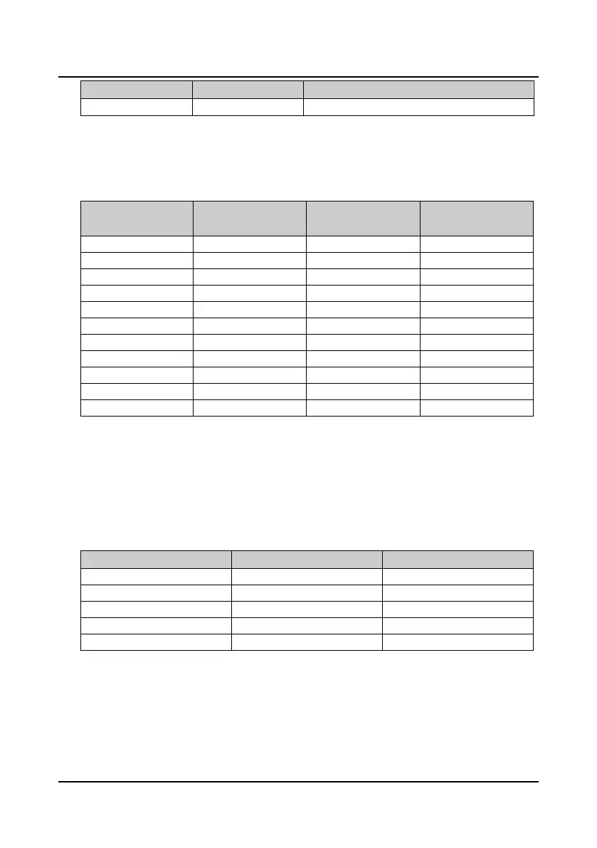
7. Address Mapping
The inverter’s function parameters, control parameters and status parameters are all mapped as
MODBUS’s read-write register. And their group numbers are mapped as the higher bytes of
register address while the relationships are shown as below table.
High bytes of register
address
Group number
High bytes of register
address
Group number
0x00 F00 0x01 F01
0x02 F02 0x03 F03
0x04 F04 0x05 F05
0x06 F06 0x07 F07
0x08 F08 0x09 F09
0x0a F10 0x0d F13
0x0f F15 0x10 F16
0x11 F17 0x12 F18
0x13 F19 0x14 F20
0x17 F23
0x32 Control parameter group 0x33 Status parameter group
Their intergroup indexes are mapped as the lower bytes. Please refer to the instruction manual
for more details on function parameters F00
-
F23.
The users can realize the inverter’s starting, stopping and running speed setting through the
control parameter, and obtain the inverter’s running frequency, output current, etc. through
indexing the inverter’s status parameters.
1) Control parameters
The inverter’s control parameter intergroup indexes are as follows:
Register address Parameter name Retained or not at power loss
0x3200 Control command character No
0x3201 Running frequency setting No
0x3202 Auxiliary running frequency setting No
0x3203 Reserved
0x3204 Virtual terminal control setting No
 Loading...


