Chapter 6 Function Introduction Shenzhen Hpmont Technology Co., Ltd
―88― HD30 Series Inverters User Manual
No. Name Description Range
factory setting
F15.18 DO1 terminal function selection 0
37
0
DO2 terminal function selection
F15.20 RLY1 relay function selection 0
37
31
RLY2 relay (extension relay) function selection
F15.22 RLY3 relay (extension relay) function selection 0
37
0
RLY4 relay (extension relay) function selection
0: Reserved. There is no output function and action of the output terminal.
1: Inverter ready. The inverter completes power on and no fault occurs, then it can normally run the
indicating signal.
2: Inverter is running. The inverter is in run status and output indicatiing signal.
3: Inverter is forward running. The inverter is forward running the indicating signal.
4: Inverter is reverse running. The inverter is reverse running the indicating signal.
5: Inverter is DC braking. The inverter is DC braking the indicating signal.
6: Inverter is in zero-frequency status. In the zero-frequency range the inverter’s output frequency
(including in stop status) outputs the indication signal.
• Refer to parameters F15.28 and F15.29.
7: Inverter is in zero-frequency running. In the zero-frequency range the inverter’s output frequency
outputs the indicating signal.
• Refer to parameters F15.28 and F15.29.
8: Reserved.
9,10: Frequency detection threshold (FDT1,FDT2).
• Refer to parameters F15.31-F15.35.
11: Frequency arriving signal (FAR). Indication signal will be output when the inverter’s output
frequency is within the FAR range.
• The FAR is set by F15.27 (FAR range).
12: Limitation of upper limit of frequency. The indicating signal will be output if the setting frequency is
beyond the upper limit of frequency.
13: Limitation of lower limit of frequency. The indicating signal will be output if the setting frequency is
lower than the lower limit of frequency.
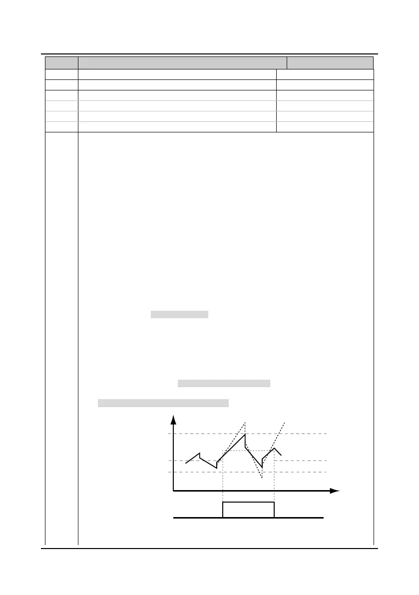
14: Limitation of upper/lower limits of wobble frequency.
• If the wobble frequency calculated by the central frequency is higher than upper limit of
frequency or lower than the lower limit of frequency (F00.09), signal will be output, as shown in
figure.
• When F07.00 = 1 (using the wobble function), this terminal function is enabled.
F00.09
Running frequency
Lower limit of frequency
Central frequency
Upper limit of frequency
Before limiting amplitude
After limiting amplitude
Wobble frequency
Time
Output signal
Limitation of upper/lower limits of wobble frequency
 Loading...


