Shenzhen Hpmont Technology Co., Ltd Chapter 6 Function Introduction
HD30 Series Inverters User Manual ―87―
No. Name Description Range
factory setting
• 0 means positive logic while 1 means negative logic.
Note: Only when using HD30-EIO and HD30-WIO will DI7
DI9 be enabled.
• FWD can be selected by multi-function input terminal DIi and represented as “FWD”. At this time,
the function of this terminal should be defined as No. 2 function.
• REV can be selected by multi-function input terminal DIi and represented as “REV”. At this time,
the function of this terminal should be defined as No. 3 function.
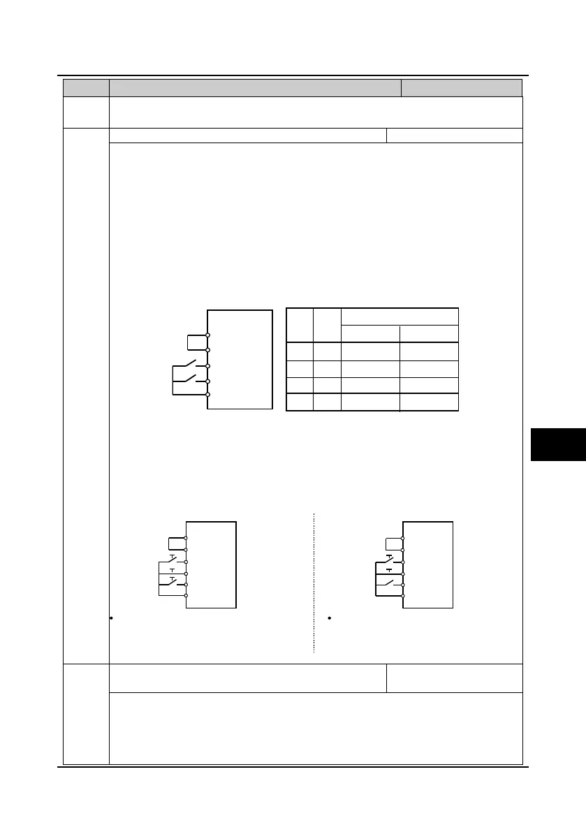
This function defines the four control modes via the external terminals.
0: Two-wire operation mode 1.
1: Two-wire operation mode 2.
• When stop command coming from other sources makes the inverter stopping though the
terminal logic enabled in the terminal control mode, there is no run command even the control
terminal FWD/REV are still valid.
• If you want the inverter to run again, you should trigger the active FWD and REV. For example:
The terminal function set as 12, 41-45 or PLC stop after single cycle.
2: Three-wire operation mode 1.
• If the shift between SB2 and SB3 is disabled, the inverter will hold the control mode.
3: Three-wire operation mode 2.
• If SB2 changes from enabled into disabled, the inverter will keep the same mode.
• DIi can be selected by the multi-function input terminal DIi. At this time, the function of this
terminal should be defined as No. 4 function of “three-wire operation”.
F15.17 Terminal operating selection due to fault of external
equipment
0
3
0
When there is fault of external equipment, it can select protection.
0: Coast to stop.
1: Emergency stop.
2: Decelerate to stop.
3: Continue to run.
P24
SEL
FWD
REV
COM
K1
K2
K1K2
00
01
11
10
Mode 2Mode 1
Run command
Stop
Stop
Stop
Stop
Forward
Reverse
Forward
Reverse
SB1
SB2
SB3
K
SB1
SB2
Three-wire operation mode 1
SB1:Normally-closed stop button (effective at the falling edge)
SB2:Normally-open forward button (effective at the risling edge)
SB3:Normally-open reverse button (effective at the rising edge)
K:Direction selection button (level on)
COM
REV
DIi
FWD
SEL
P24
COM
REV
DIi
FWD
SEL
P24
SB1:Normally-closed stop button (effective at the falling edge)
SB2:Normally-open run button (effective at the risling edge)
K = 0 (forward) K = 1 (reverse)
Three-wire operation mode 2
6
 Loading...


