Chapter 6 Function Introduction Shenzhen Hpmont Technology Co., Ltd
―76― HD5L Series Controller User Manual
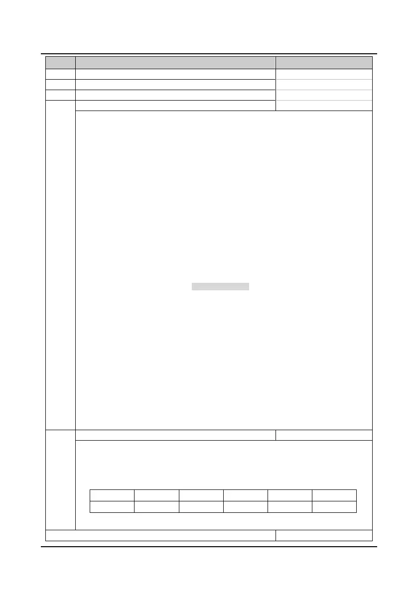
Code Name Description Range
factory setting
F12.17 RLY1 relay function 0
19
14
RLY2 relay (I/O card relay) function
F12.19 RLY3 relay (I/O card relay) function 0
19
0
RLY4 relay (I/O card relay) function
0: Disable. The output terminals will be at no function state and no any action.
1: Controller is ready.
• Signal ON will be output if controller has no error.
2: Controller is running.
• Indication signal will be output if controller is at running state.
3: Controller is at zero-speed running.
• ON signal will be output if controller output speed is zero but at running state.
4: Zero-speed.
• ON signal will be output if controller output speed is zero.
5: Contactor output control.
• This function is used to open/close the output contactor.
6: Brake output control.
• This function is used to open/close the brake.
7,8: FDT1, FDT2.
• Refer to parameters F05.12-F05.13.
9: Speed arrived signal (FAR).
• The indication signal will be output when the controller’s output frequency is within the FAR
range. The detect range is set by F05.16 (FAR range).
• The indication signal will be output too after the controller stops.
10: Up signal output.
• When the elevator is at up running, the controller will output ON signal.
11: Down signal output.
• When the elevator is at down running, the controller will output ON signal.
12: Under-voltage.
• ON signal will be output when the controller is during under-voltage state.
13: Reserved.
14: Controller fault.
• ON signal will be output when the controller is faulty.
15: Elevator stop.
• When the elevator stops, the controller will stop and output an 2s pulse. The controller will
disable the running command according to this signal.
16-19: Reserved.
Output terminal logic setting
It defines that each bit (binary) of this function represents different physical sources.
• Positive logic: When multi-function input terminals are connected to corresponding common port,
this logic is enabled. Otherwise the logic is disabled.
• Negative logic: When multi-function input terminals are connected to corresponding common port,
this logic is disabled. Otherwise the logic is enabled.
Bit5 Bit4 Bit3 Bit2 Bit1 Bit0
RLY4 RLY3 RLY2 RLY1 DO2 DO1
• 0 represents positive logic, while 1 represents negative logic.
F12.22
F2.24 Reserved

 Loading...