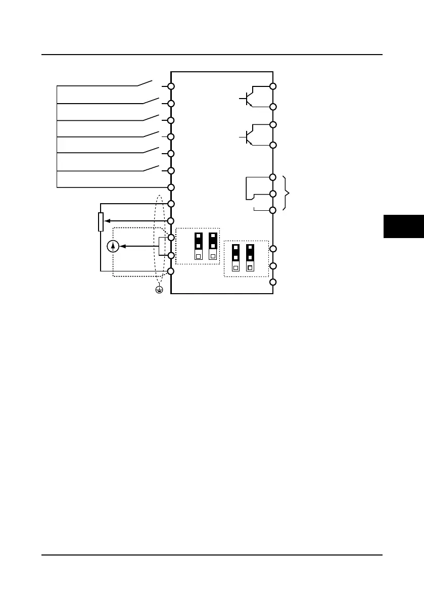
EasyManuals Logo

hpmont HD5L series User Manual

hpmont HD5L series
155 pages
To Next Page IconTo Next Page
To Previous Page IconTo Previous Page
Page #30 background imageLoading...
Page #30 background image
Shenzhen Hpmont Technology Co., Ltd Chapter 4 Electrical Installation
HD5L Series Controller User Manual 21
4.4.4 Control Terminal Connection
Figure 4-6 HD5L control circuit connection diagram
DI1
DO2
DO1
CME
R1A
R1C
R1B
GND
AO1
AO2
DI2
DI3
DI4
DI5
DI6
COM
AI1
AI2
+10
HD5L
Control board
AI3
GND
COM
PE
CN5
1
3
CN6
1
3
CN7
1
3
CN8
1
3
Multi-function input terminal 1
Multi-function input terminal 2
Multi-function input terminal 3
Multi-function input terminal 4
Multi-function input terminal 6
Multi-function input terminal 5
Digital ground
DO1 reference ground
DO2 reference ground
AI 1
AI 2
Analogue ground
Analogue ground
Analogue output channel 2
Analogue output channel 1
Programmable relay output
Programmable open-collector
output channel 1
Programmable open-collector
output channel 2
AI
3
Shielded cable
4

Table of Contents

Questions and Answers:

Question and Answer IconNeed help?

Do you have a question about the hpmont HD5L series and is the answer not in the manual?

hpmont HD5L series Specifications

General IconGeneral
Brandhpmont
ModelHD5L series
CategoryController
LanguageEnglish

Related product manuals