4 Installation and commissioning
HSD S.p.A. © - 0104h03a.fm100713
55
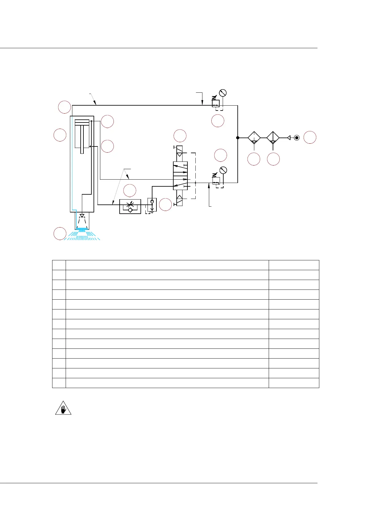
Figure 4: exemplary pneumatic layout of the ES330 "liquid" electrospindles
1 Air inlet for tool release and cone cleaning 6 bar - 87 PSI
2
Tool locking air inlet (piston return) 6 bar - 87 PSI
3
Double effect piston
4 Unidirectional flow regulator for regulating the ejection speed
5
Rapid discharge valve
6 Monostable 5-2 valve with electro-pneumatic control and spring return
7 Pressure regulator with pressure switch calibrated to 6 bar
8 Oil separator filter 0.1 µm.
9 Pre-filter 5 µm
10 Mains power supply
11 Continuous flow of pressurisation air
12 Pressurisation air inlet 0.5 bar - 7.3 PSI
13 Pressure regulator with pressure switch calibrated to 0.5 bar
THE PROPOSED CIRCUIT IS PURELY EXEMPLARY.
1
13
8 9
10
3
4
6
7
2
11
12
O6x4
5
6 Bar
0,5 Bar