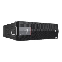
Figure 6-4 Output terminals of the I-type DC PDU
NEG11 (-) NEG 12 (-) RTN 11 (+) RTN 12 (+) NEG 21 (-) NEG 22(-) RTN 21 (+) RTN 22 (+) NEG 31 (-) NEG 32(-) RTN 31 (+) RTN 32 (+) NEG 41( -) NEG 42 (- ) RTN 41 (+) RTN 42 (+)
NEG 11 (-) NEG 12(-) RTN 11 (+) RTN 12 (+) NEG 21 ( -) NEG 22(-) RTN 21 (+) RTN 22(+) NEG 31 ( -) NEG 32(-) RTN 31 (+) RTN 32 (+) NEG 41(-) NEG 42(-) RTN 41 (+) RTN 42 (+)
-48 V/-60 V Output Control Switch
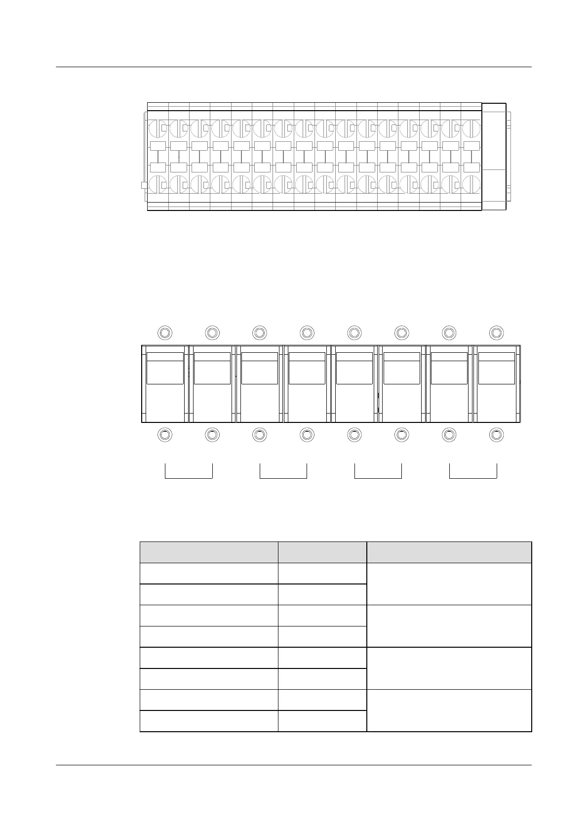
Figure 6-5 shows the -48 V/-60 V output control switch of the I-type DC PDU.
Figure 6-5 -48 V/-60 V output control switch of the I-type DC PDU
SW11 SW12 SW21 SW22 SW31 SW32 SW41 SW42
ON ON ONONONONON ON
OFF OFFOFFOFFOFFOFFOFFOFF
Frame1 Frame4Frame3Frame2
Table 6-2 Mapping between the output terminals, control switches and service subracks
Terminal Silkscreen
Control Switch Load
NEG11 (-), RTN11 (+) SW11 The first service subrack (from
bottom to top)
NEG12 (-), RTN12 (+) SW12
NEG21 (-), RTN21 (+) SW21 -
NEG22 (-), RTN22 (+) SW22
NEG31 (-), RTN31(+) SW31 The second service subrack (from
bottom to top)
NEG32 (-), RTN32 (+) SW32
NEG41(-), RTN41(+) SW41 -
NEG42 (-), RTN42(+) SW42
SmartAX MA5600T/MA5603T/MA5608T Multi-service
Access Module
Hardware Description
6 Electromechanical Device
Issue 24 (2018-07-30) Huawei Proprietary and Confidential
Copyright © Huawei Technologies Co., Ltd.
912

 Loading...