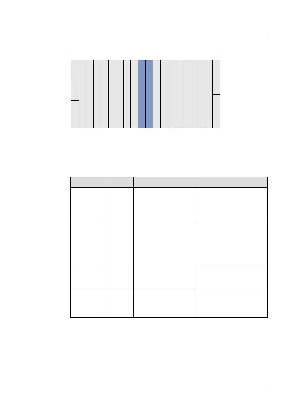
Figure 2-3 Configuration of boards in the ETSI service subrack
S
e
r
v
i
c
e
b
o
a
r
d
S
e
r
v
i
c
e
b
o
a
r
d
S
e
r
v
i
c
e
b
o
a
r
d
S
e
r
v
i
c
e
b
o
a
r
d
S
e
r
v
i
c
e
b
o
a
r
d
S
e
r
v
i
c
e
b
o
a
r
d
S
e
r
v
i
c
e
b
o
a
r
d
S
e
r
v
i
c
e
b
o
a
r
d
C
o
n
t
r
o
l
b
o
a
r
d
C
o
n
t
r
o
l
b
o
a
r
d
S
e
r
v
i
c
e
b
o
a
r
d
S
e
r
v
i
c
e
b
o
a
r
d
S
e
r
v
i
c
e
b
o
a
r
d
S
e
r
v
i
c
e
b
o
a
r
d
S
e
r
v
i
c
e
b
o
a
r
d
S
e
r
v
i
c
e
b
o
a
r
d
S
e
r
v
i
c
e
b
o
a
r
d
S
e
r
v
i
c
e
b
o
a
r
d
121
22
2 3 4 5 6 7 8 9 10 11 12 13 14 15 16 17 18 19
20
G
P
I
O
G
I
U
G
I
U
0
P
o
w
e
r
P
o
w
e
r
Fan tray
Table 2-4 lists the configuration of boards in the ETSI service subrack. For details, see 3.4
Board Configuration(MA5600T/MA5603T).
Table 2-4 Boards in the ETSI service subrack
Slot Type
Slot Supported Board Remarks
Control board
(SCU) slot
9,10 Control board Two slots must be configured
with the same control board.
You are advised to configure 2
control boards working in
active/standby mode.
Uplink
interface
board (GIU)
slot
19,20 Uplink interface board Mixed configuration of
upstream interface boards is
supported; however, it is
recommended to use the same
upstream interface board in the
configuration.
Power board
slot
21,22 Power board It is recommended to configure
the same power board in the
two slots.
Universal
interface
board (GPIO)
slot
0 Universal interface board -
SmartAX MA5600T/MA5603T/MA5608T Multi-service
Access Module
Hardware Description
2 Subrack and Chassis
Issue 24 (2018-07-30) Huawei Proprietary and Confidential
Copyright © Huawei Technologies Co., Ltd.
74
 Loading...