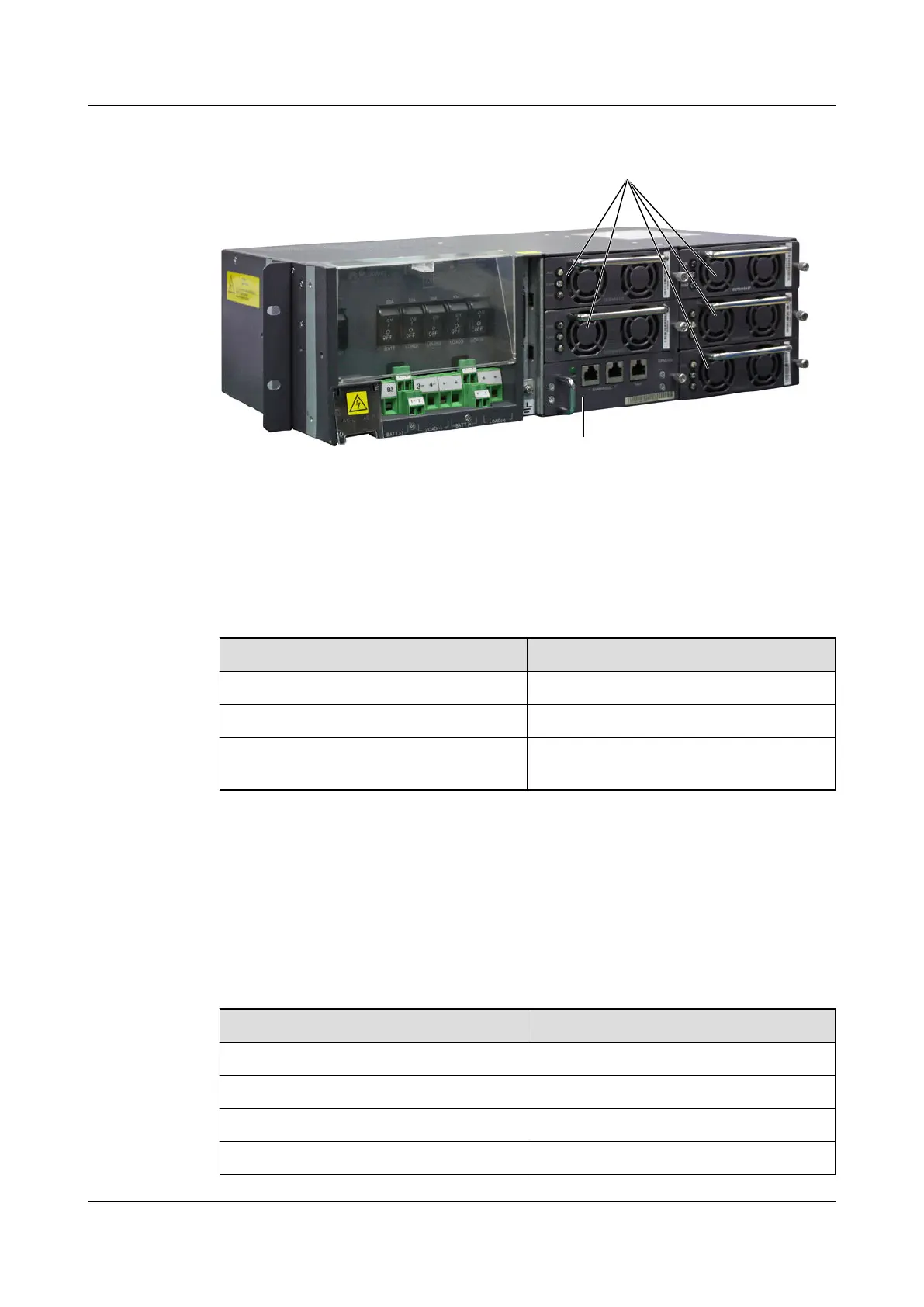
Figure 6-24 Appearance of the EPS75-4815AF power system
Rectifier module
Monitoring module
Configuration
Table 6-21 lists the component configuration of the EPS75-4815AF power system.
Table 6-21 Component configuration of the EPS75-4815AF power system
Component Name
Configuration
GERM4815T rectifier module 2 to 5 (optional)
EPMU02 monitoring module 1
Rack-EPS75-4815AF AC/DC power supply
unit
1
The EPS75-4815AF power system can be configured with five rectifier modules, which are
connected in parallel for output.
Table 6-22 shows the mapping between the number of rectifier modules in the
EPS75-4815AF power system and the maximum output current.
Table 6-22 Mapping between the number of rectifier modules in the EPS75-4815AF power
system and the maximum output current
Number of Rectifier Modules
Maximum Output Current
1 15 A
2 30 A
3 45 A
4 60 A
SmartAX MA5600T/MA5603T/MA5608T Multi-service
Access Module
Hardware Description
6 Electromechanical Device
Issue 24 (2018-07-30) Huawei Proprietary and Confidential
Copyright © Huawei Technologies Co., Ltd.
936

 Loading...