6
Example of System Operation
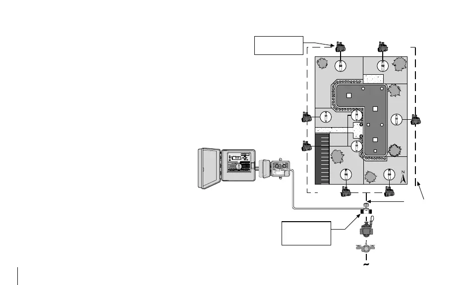
In this illustrative example of a small commercial site, the
Flow-Clik sensor is connected to the mainline pipe that
provides water to the system control valves. Because it
is installed immediately down stream of the master valve,
it will provide the added protection of shutting down the
irrigation system if a mainline break should occur.
The Flow-Clik can be set to automatically shut off the
system whenever actual flow within the system exceeds the
flow of the system’s highest flow zone. During installation
of the Flow-Clik, a calibration procedure (see Cali-
brating the Flow-Clik) is used to set the Flow-Clik
at a level of flow dictated by the highest flow zone.
If the system flow exceeds the “calibrated” flow by
a pre-determined amount, the Interface Box will
signal an overflow condition is occurring.
The figure to the right shows an example of an application
using the Flow-Clik sensor. In this example, the valve that
commands the highest flow is valve number 4, which has a
total flow rate of 18.9 gallons per minute (GPM). The user
would turn this valve on and calibrate the Flow-Clik to this
zone. If flow exceeds 18.9 gpm, a signal will be sent to the
Interface Box which would communicate to the controller
SYSTEM OVERVIEW AND FLOW-CLIK OPERATION (continued) ............
ICC Controller
®
® ®
®
®
®
®
®
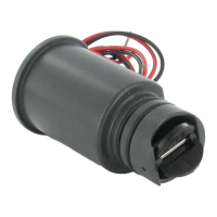
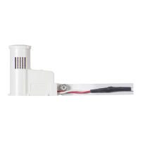
Flow-Clik Sensor
Master Valve
Back Flow Preventer
Point of Connection
Flow-Clik
Interface
Valve 4 has been
determined to have the
highest flow
Wire
Mainline Pipe
Flow-Clik is located on
mainline to shut down
the system if the
mainline is ruptured
Valve 4
(18.9 GPM)
Valve 6
(17.0 GPM)
Valve 1
(13.0 GPM)
Valve 7
(16.0 GPM)
Valve 2
(14.0 GPM)
Valve 3
(15.0 GPM)
Valve 5
(16.0 GPM)