1.3
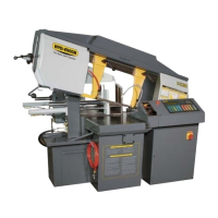
INSTALLATION OF THE SHUTTLE GUARD
The shuttle guard of the S23A has been removed for shipping. This guard must be assembled back on to the machine
before the POWER WIRING CONNECTIONS are completed.
M8 BOLT
M12 BOLTS
FOUNDATION, LEVELLING AND ANCHORING
Machine location should be carefully selected. A at concrete oor area should be chosen. It should have enough free
space surrounding the machine to enable free access for safe operation and maintenance. The machine should be lev-
eled in both directions (from side to side & from front to back). Six leveling screws used for securing the machine to the
pallet during transport, should be installed, one in each corner of the machine base. It might be required to place steel
plates under leveling bolts to prevent their sinking into the concrete oor. In cases when the machine is to be anchored
permanently, anchoring holes are provided. They are located next to the leveling screw holes. The larger diameter hole
is used for retaining during shipping and for use with concrete oor anchors. The smaller diameter threaded hole at each
corner, are used for leveling the saw.
Using a level on the machine out-feed table, level machine front to back and side to side.
NOTE: In some cases leveling the saw infeed with a slight slope towards the blade is recommended. This will prevent
coolant from running down the raw stock. (This is especially true when cutting tubing or bundles).
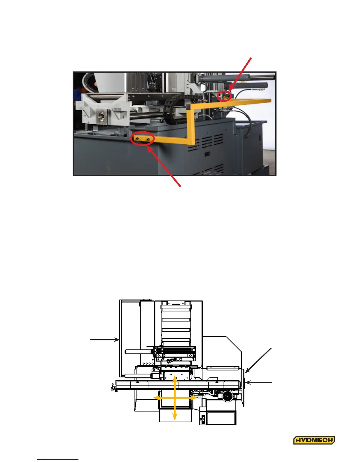
SHUTTLE GUARD
COOLANT TANK
DRIVE SIDE
COOLANT COVER
 Loading...