3.6
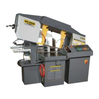
DRIVE WHEEL ADJUSTMENT
The Drive Wheel adjustment is closely linked to adjustment of the Idler Wheel. The purpose of the adjustment is to ensure
that the back of the blade remains about 0.58” - 0.62” (14.7 - 15.7 mm) away from the back edge of the wheel during rota-
tion.
1. Open wheel cover.
2. Loosen all the screws on the wheel and manually move it in or out until the blade is correctly distanced from
the wheel ange.
3. Restore the machine and run blade for few wheel rotations.
4. Check the distance between the blade and wheels ange.
5. If necessary repeat steps until proper gap is achieved.
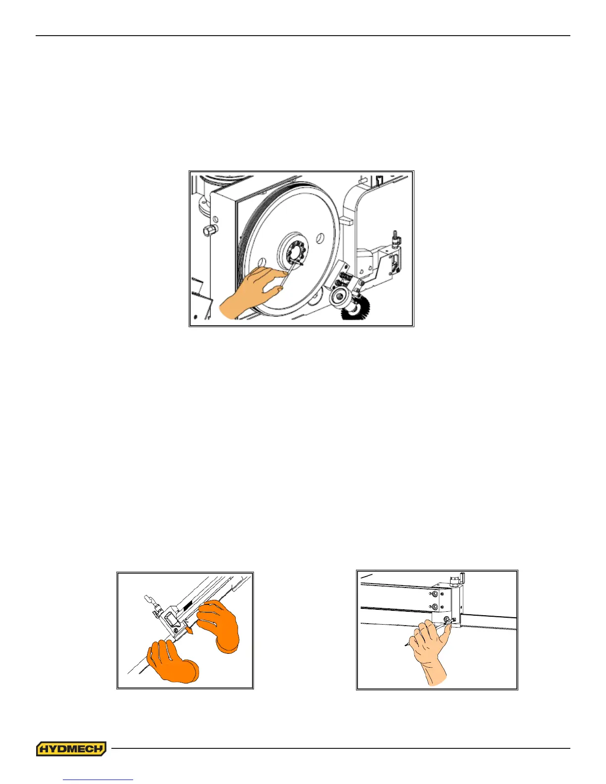
BLADE GUIDE ADJUSTMENT
At the bottom of the guide arms are the blade guide block assemblies with carbide pads. These assemblies will need to be
adjusted occasionally as the carbide pads become worn, or if a blade with dierent thickness is used. To adjust properly,
follow this simple procedure.
1. Make sure there is a small amount of play between the blade and guide carbides. The blade band should be snug
but able to move freely up and down.
2. If the amount of play is not sucient for the blade to run smoothly, adjust the locking torque of the screws with an
Allen key.
 Loading...